Oil-driven differential-speed-type multi-rotor agricultural spraying aircraft of vertical type engine central transmission
A central transmission and engine technology, applied in the field of flight platforms and oil-driven differential multi-rotor agricultural spraying aircraft, can solve the problems of high spraying cost, complex mechanical mechanism, high cost, etc. The effect of performance improvement
- Summary
- Abstract
- Description
- Claims
- Application Information
AI Technical Summary
Problems solved by technology
Method used
Image
Examples
specific Embodiment approach 1
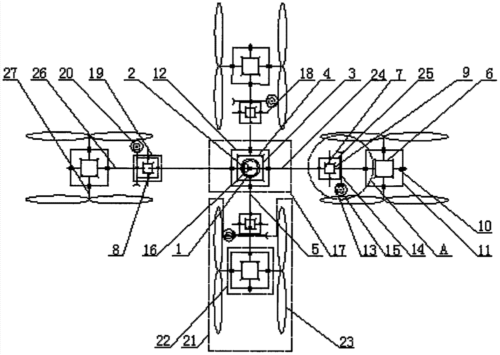
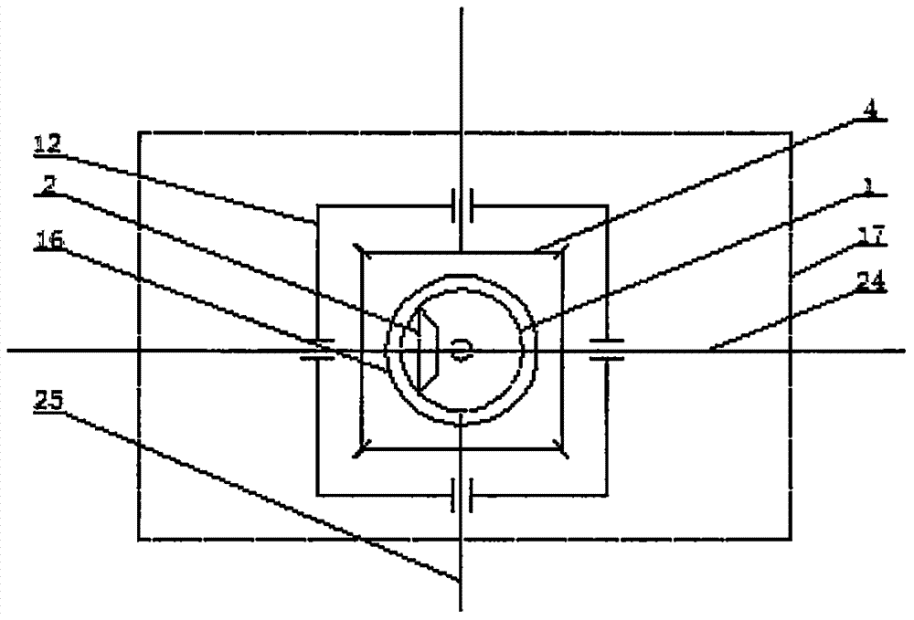
[0016] Specific implementation mode one: as Figure 1 ~ Figure 3 As shown, this embodiment discloses an oil-driven differential multi-rotor agricultural spraying aircraft driven by the engine center, including an engine 16, a central bevel gear transmission box 17, four bevel gear differential transmission boxes 19, four worm gears Transmission mechanism 20 and four rotor transmission mechanisms 21, each of the rotor transmission mechanisms 21 includes a rotor bevel gear transmission box 22 and two rotors 23, and the central bevel gear transmission box 17 includes the central transmission box body 12 , horizontal central shaft 24, central driving bevel gear 1, central driven bevel gear 2, two central bevel gears one 3, two central bevel gears two 4 and two central output shafts 5, the horizontal central shaft 24 Both ends pass through the central transmission box 12 and are arranged outside the central transmission box 12. The horizontal central axis 24 is connected to the cen...
specific Embodiment approach 2
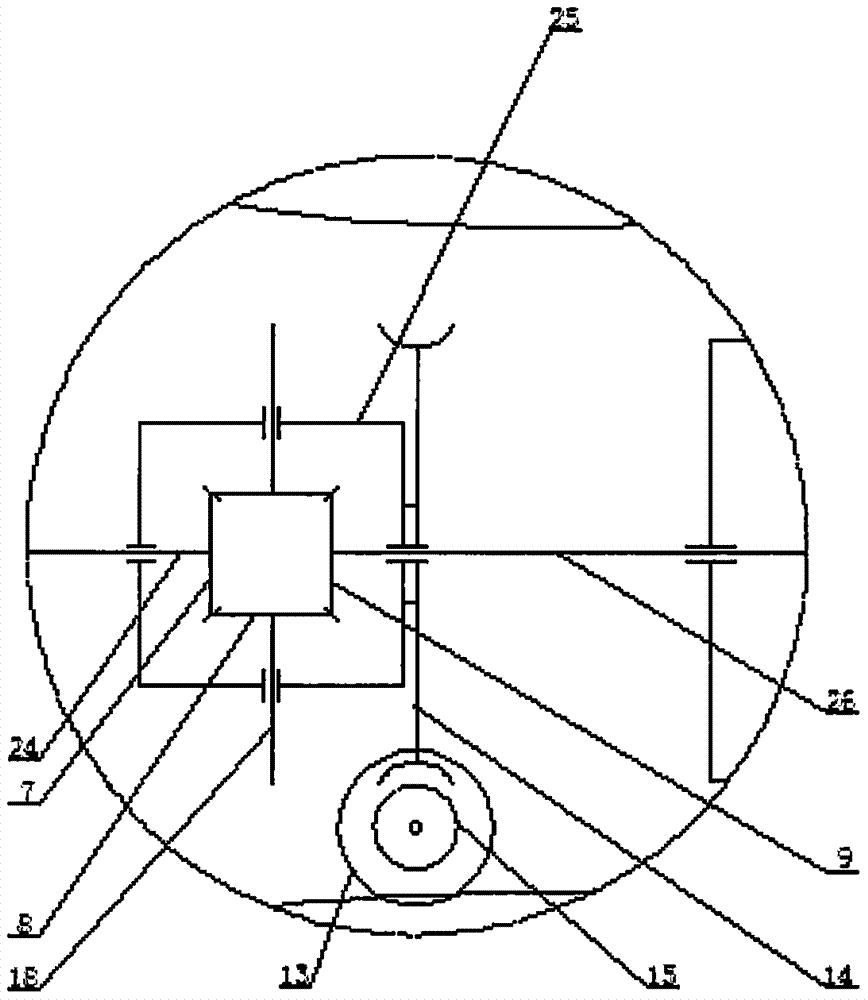
[0018] Specific implementation mode two: as figure 1 and figure 2 As shown, the oil-driven differential multi-rotor agricultural spraying aircraft with engine center transmission described in Embodiment 1, each of the bevel gear differential transmission boxes 19 includes a bevel gear differential box body 25, a bevel gear-1 7. Bevel gear two 9, two bevel gear three 8 and two bevel gear support shafts 18, the bevel gear one 7, bevel gear two 9 and two bevel gear three 8 are all arranged in the bevel gear differential box In 25, on two described bevel gear support shafts 18, a bevel gear three 8 is respectively rotated, and the two bevel gear three 8 are meshed with bevel gear one 7 and bevel gear two 9 simultaneously, and the two bevel gears The support shafts 18 are all rotatably connected with the side walls of the bevel gear differential case 25 .
specific Embodiment approach 3
[0019] Specific implementation mode three: as figure 1 and figure 2 As shown, the oil-driven differential multi-rotor agricultural spraying aircraft with engine center transmission described in the second specific embodiment, each of the rotor bevel gear transmission boxes 22 of the rotor transmission mechanism 21 includes a rotor bevel gear box body 11, Rotor input shaft 26, rotor bevel gear support shaft 10, four rotor bevel gears 6 and two rotor output shafts 27, the four rotor bevel gears 6 are all arranged in the rotor bevel gear box 11, and the rotor The other end of the input shaft 26 passes through the bevel gear box 11 and is fixedly connected with one of the bevel gears 6 of the four bevel gears 6, and the input shaft 26 is rotationally connected with the bevel gear box 11. The gear 6 meshes with two of the remaining three rotor bevel gears 6 at the same time, and the two of the rotor bevel gears 6 mesh with the remaining one of the rotor bevel gears 6, and the two...
PUM
 Abstract
Description
Claims
Application Information
 - R&D
- Intellectual Property
- Life Sciences
- Materials
- Tech Scout
- Unparalleled Data Quality
- Higher Quality Content
- 60% Fewer Hallucinations
Browse by: Latest US Patents, China's latest patents, Technical Efficacy Thesaurus, Application Domain, Technology Topic, Popular Technical Reports.
© 2025 PatSnap. All rights reserved.Legal|Privacy policy|Modern Slavery Act Transparency Statement|Sitemap|About US| Contact US: help@patsnap.com


