
Positioning and centering combination clamping device

A technology of clamping device and centering cone, which is applied in the direction of positioning device, clamping device, clamping, etc., can solve the problems that the product is difficult to meet the product design requirements, the difference of positioning and clamping device is large, and the wall thickness is small. Achieve the effects of increasing overall rigidity, uniform wall thickness difference, and improving machining accuracy

Pending Publication Date: 2017-10-10
江南工业集团有限公司
View PDF8 Cites 2 Cited by
  • Summary
  • Abstract
  • Description
  • Claims
  • Application Information

AI Technical Summary

Problems solved by technology

Long cylindrical thin-walled parts have attracted the attention and attention of the machining industry due to their small wall thickness (≤2mm), weak rigidity and easy deformation. Due to different product shapes and processing methods, their positioning and clamping devices are also different. Larger, the processed product is difficult to meet the product design requirements

Method used


Image

  • Positioning and centering combination clamping device
  • Positioning and centering combination clamping device

Examples


Embodiment Construction

[0015] The present invention will be described in further detail below in conjunction with the accompanying drawings.

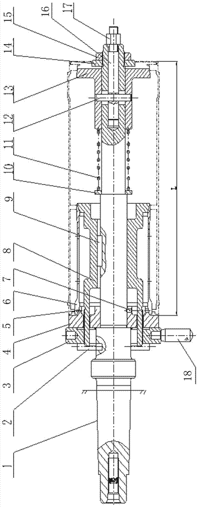
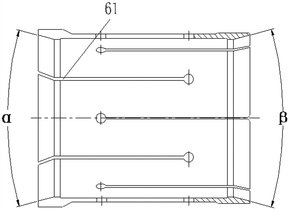
[0016] Such as figure 1 As shown, the present invention includes shaft 1, fixed pin 2, large nut 3, fixed cone 4, pin 5, expansion spring 6, set screw 7, movable cone 8, adjusting washer 10, spring 11, pin 12, fixed Heart cone 13, retaining ring 14, nut 15, mandrel 16, nut 17, handle 18. The fixed cone 4 and the movable cone 8 are arranged on the shaft, and the cone faces on the fixed cone 4 and the movable cone 5 are arranged oppositely. On axis 1, it is possible to move along axis 1. The front end of the movable cone 8 is provided with threads, and passes through the through hole on the fixed cone to be connected with the big nut 3 . The side wall of the big nut 3 is provided with a handle 18, which is convenient for the big nut 3 to rotate and fasten the workpiece to be processed. The two ends of expansion spring 6 are respectively placed on the conica...


PUM


Abstract

The invention discloses a positioning and centering combination clamping device. The positioning and centering combination clamping device comprises a shaft, a big nut, a fixed cone, a rising spring, a movable cone, a centering cone dish and a blocking ring. The fixed cone and the movable cone are arranged on the shaft. The cone surfaces of the fixed cone and the movable cone are arranged oppositely. The front end of the movable cone penetrates through a through hole on the fixed cone and is connected with the big nut. The two ends of the rising spring are correspondingly arranged on the cone surfaces of the fixed cone and the movable cone. The centering cone dish is installed at the back end of the shaft. The back end of the shaft is provided with the blocking ring. The blocking ring is positioned in the axial direction on the shaft through the nut. According to the positioning and centering combination clamping device, a way of rising spring bi-directional positioning clamping is adopted, a rigidity cone dish bearing is designed at the cantilever ends of machined parts in an auxiliary mode, deformation of products caused by machining stress is overcome, the uniform wall thickness difference of the whole section of the machined parts is ensured, and the positioning and centering combination clamping device has the characteristics of being convenient to operate, safe, reliable and the like.

Description

technical field [0001] The invention belongs to the technical field of thin-wall parts processing equipment, and in particular relates to a positioning and centering combined clamping device. Background technique [0002] At present, with the continuous development of mechanical processing technology for military and civilian products, the processing accuracy of products has been continuously improved. With the development of modern industrial technology, the design of product structure is becoming more and more sophisticated, which requires both light weight and reliability to increase the payload, thus putting forward higher requirements for mechanical processing equipment. Long cylindrical thin-walled parts have attracted the attention and attention of the machining industry due to their small wall thickness (≤2mm), weak rigidity and easy deformation. Due to different product shapes and processing methods, their positioning and clamping devices are also different. Larger...

Claims


Application Information

Patent Timeline
Patent Type & Authority Applications(China)
IPC IPC(8): B23Q3/00
CPCB23Q3/00B23Q2703/10
Inventor 杨建贺刘进军刘永红丁震陈小明王高锋
Owner 江南工业集团有限公司
Learn More