
Laser underwater explosion emission propulsion method in tube

A technology of underwater explosion and laser, which is applied in the direction of educational appliances, instruments, teaching models, etc., can solve the problems of low energy utilization rate and small specific impulse, and achieve the effects of reducing the total weight, effectively separating, and reducing energy dissipation

Inactive Publication Date: 2017-09-29
BEIJING RES INST OF MECHANICAL & ELECTRICAL TECH
View PDF8 Cites 8 Cited by
  • Summary
  • Abstract
  • Description
  • Claims
  • Application Information

AI Technical Summary

Problems solved by technology

[0003] Compared with other branches of laser propulsion, the research work on laser underwater explosive propulsion is still very rare, and it mainly stays in the demonstration experiment stage. Laser propulsion in open water mainly relies on the instantaneous impact loading brought by the ablation of liquid working fluid. effect, and the free dissipation of subsequent product bubble pulsation energy cannot produce continuous and effective thrust on the vehicle
At present, although the laser underwater explosion propulsion has obtained a higher impulse coupling coefficient than the laser ablation of the target plate in air and vacuum media, it still has the problems of small specific impulse and low energy utilization.
Therefore, how to further improve the efficiency of the laser underwater explosion propulsion method can be achieved by improving and optimizing the launching device. There is no relevant research report on the launch direction in the tube. It is necessary to study its propulsion launch method to provide a more feasible propulsion launch method and application direction

Method used


Image

  • Laser underwater explosion emission propulsion method in tube
  • Laser underwater explosion emission propulsion method in tube
  • Laser underwater explosion emission propulsion method in tube

Examples


Embodiment Construction

[0022] In order to make the purpose, content and advantages of the present invention clearer, the specific implementation manners of the present invention will be further described in detail below in conjunction with the accompanying drawings and embodiments.

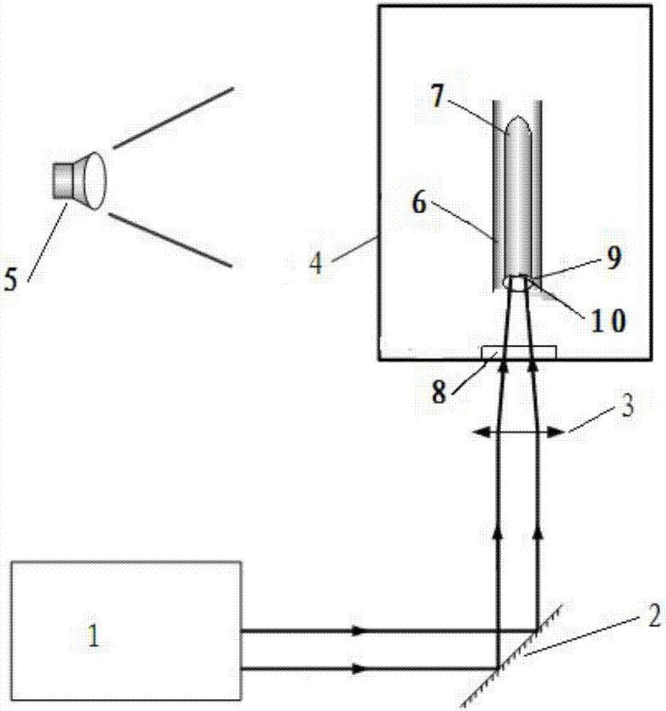
[0023] In order to achieve the above object, the present invention firstly provides a vertical launch propulsion system for laser underwater explosion in a pipe, referring to figure 1 As shown, the system includes: a laser 1 for emitting laser beams; a launching platform, including a launching water tank 4, in which a transparent water medium is contained in the launching water tank 4, a launching tube 6 is arranged in the water medium, and a navigation body 7 is slidably arranged in the launching tube 6 The laser beam passes through the transparent water medium to irradiate the tail of the vehicle 7 to induce the ablation of the working fluid at the tail of the vehicle 7, and the laser interacts with the ablation gas to...


PUM


Abstract

The present invention discloses a new method for emission and tube exit of navigation body through laser underwater explosion emission propulsion in a tube. High-energy laser is focused to the tail portion of a model to generate detonation wave and high-temperature and high-pressure product bubbles, and detonation wave propagation and bubble pulsation are performed to generate thrust in the emission tube constraint condition so as to realize tube exit of the navigation body through vertical emission. The laser underwater explosion energy is intensively effected on the motion of the navigation body so as to greatly reduce the energy dissipation, provide enough thrust effect and duration and reach the energy requirement of tube exit of the navigation body. Compared to a current chemical fuel emission propulsion method, the laser underwater explosion emission propulsion method in a tube can realize effective separation of the fuel, the propeller and the navigation body so as to effectively reduce the total weight of the navigation body and realize the effect of increasing the effective load.

Description

technical field [0001] The invention belongs to the technical field of laser explosion propulsion, and relates to an underwater laser explosion emission and propulsion method in a tube. Background technique [0002] Laser underwater explosion propulsion is a challenging new concept propulsion technology, which mainly uses laser-sustained underwater detonation and subsequent oscillation of product bubbles to realize the underwater motion of the vehicle. Compared with traditional chemical fuel propulsion methods, laser underwater explosive propulsion has high safety, easy control of thrust output, flexible and micro propulsion, and shows good development prospects. [0003] Compared with other branches of laser propulsion, the research work on laser underwater explosive propulsion is still very rare, and it mainly stays in the demonstration experiment stage. Laser propulsion in open water mainly relies on the instantaneous impact loading brought by the ablation of liquid worki...

Claims


Application Information

Patent Timeline
Patent Type & Authority Applications(China)
IPC IPC(8): G09B23/00
CPCG09B23/00
Inventor 张健赵宇王伟操小龙
Owner BEIJING RES INST OF MECHANICAL & ELECTRICAL TECH
Learn More