Artificially excavated riding well and construction method thereof

A construction method, the technology of riding a well, is applied in the field of inspection wells, which can solve the problems of long construction period, unfavorable construction for workers, and large engineering volume, and achieve the effects of ensuring construction quality, convenient drainage, and less water seepage

Inactive Publication Date: 2017-09-29
NANTONG SHIPPING COLLEGE
View PDF7 Cites 3 Cited by
  • Summary
  • Abstract
  • Description
  • Claims
  • Application Information

AI Technical Summary

Problems solved by technology

[0003] Option 1: The amount of excavation earthwork is large, and sometimes it is restricted by the terrain, so it cannot be excavated. When the groundwater level is high, the water seepage is relatively large, and the water seeping from the expansion hole of the drag pipe will flow deep into the well, causing the well to be damaged. The bottom is full of mud, which is not conducive to the construction of workers. It is necessary to set up sumps or wells for centralized drainage, which requires a large amount of work and high costs.
[0004] Option 2: The construction of deep foundation pit support requires temporary power consumption, the power load is large, the construction period is long, and the cost is high. There is still seepage at the reaming part of the drag pipe, which needs to be blocked or drained

Method used


Image

  • Artificially excavated riding well and construction method thereof
  • Artificially excavated riding well and construction method thereof
  • Artificially excavated riding well and construction method thereof

Examples


Embodiment Construction

[0020] The following examples can enable those skilled in the art to understand the present invention more comprehensively, but the present invention is not limited to the scope of the described examples.

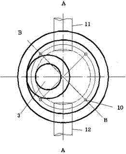
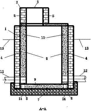
[0021] Such as Figure 1 to Figure 3 As shown, a manual excavation riding well includes a brick wall 1, a steel bar 13 is inserted in the brick wall 1, a brick well circle 2 is arranged above the brick wall 1, and a brick well circle 2 is placed above the brick wall 1. A manhole cover 3 is provided, a waterproof cement mortar layer 4 is powdered on the inside and outside of the brick well circle 2, a galvanized wire mesh 5 is arranged on the outside of the brick well circle 2; a reinforced concrete well circle 6 is arranged on the inside of the brick retaining wall 1, There is a graded crushed stone 7 behind the brick wall at the bottom of the horse-riding well and under the pipeline, and a corrugated pipe 8 is arranged inside the graded crushed stone 7, and the bottom and ...


PUM

PropertyMeasurementUnit
Diameteraaaaaaaaaa
Diameteraaaaaaaaaa

Abstract

The invention discloses an artificially excavated riding well. The artificially excavated riding well comprises a bricked protecting wall, a bricked well ring, a well lid and a reinforced concrete well ring, wherein graded broken stones are arranged at the bottom of the riding well, under a pipe and at the rear of the bricked protecting wall; a corrugated pipe is arranged in the graded broken stones; a reinforced concrete bottom plate is arranged on the graded broken stones; a certain number of PVC tubes are vertically arranged in the middle of the reinforced concrete well ring; and a pipe A and a pipe B are arranged on a side wall of the reinforced concrete well ring. The construction method comprises the following steps: (1) digging a hole artificially, and supporting by using a brick wall; (2) bricking to surround the well to the bottom of the well, laying a broken stone hardcore, burying a water channel tube, and placing a self-priming pump in the well for draining water; and (3) beginning to construct well bottom concrete cushion, and constructing the reinforced concrete bottom plate. The artificially excavated riding well has the advantages that the water percolating capacity of the structure is low, the water draining method is convenient and is good in water draining effect, the cost is low, particularly, water flowing out from the periphery of a dragging tube is guided out to guarantee that the bottom surface of concrete does not have accumulated water during pouring, and therefore, the construction quality is guaranteed.

Description

technical field [0001] The invention relates to the technical field of inspection wells for sewage pipes and drainage pipes, in particular to a manually excavated riding well and a construction method thereof. Background technique [0002] When the sewage pipes and drainage pipes are designed as drag pipes, after the construction of the drag pipes is completed, a horse-riding well needs to be constructed. The depth between the top of the drag pipe and the top of the horse-riding well is generally more than 4m, and some are even more than 8m. There are three main construction schemes for riding a horse well. One is large-scale excavation construction. After all the soil in the construction area is dug out, the construction is carried out sequentially from bottom to top; the other is deep foundation pit support construction first, such as high-pressure jet jet piles, Then manual excavation, reverse construction; the other is manual excavation, while excavating and brick suppor...

Claims


Application Information

Patent Timeline
IPC IPC(8): E03F5/02
CPCE03F5/02
Inventor 崔桂官赵苏政倪飞
Owner NANTONG SHIPPING COLLEGE
Why Eureka
Try Eureka