
Sludge stirring equipment adopting circulation type stirring processing

A mixing equipment and circulating technology, which is applied in sludge treatment, multi-stage water treatment, water/sludge/sewage treatment, etc., can solve problems such as difficulty in ensuring uniform addition of powder, loud equipment noise, and equipment damage

Inactive Publication Date: 2017-09-29
JIANGSU NATURE WAY TECH
View PDF4 Cites 0 Cited by
  • Summary
  • Abstract
  • Description
  • Claims
  • Application Information

AI Technical Summary

Problems solved by technology

Existing mixing equipment often uses traditional rotating blades for mixing treatment. During the actual treatment process, the equipment is often damaged due to repeated impacts between the mixing blades and the sludge, and at the same time, it causes problems such as excessive equipment noise.
In addition, due to the viscosity of the sludge, it is difficult to ensure a uniform mixing process during the stirring process, and it is also difficult to ensure a uniform powder addition process during the curing agent addition process

Method used


Image

  • Sludge stirring equipment adopting circulation type stirring processing
  • Sludge stirring equipment adopting circulation type stirring processing

Examples


Embodiment 1

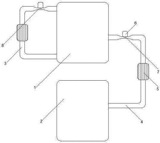
[0015] Such as figure 1 A kind of sludge agitation equipment that adopts circulation stirring treatment is shown, which includes a first treatment chamber 1 and a second treatment chamber 2, and the first treatment chamber 1 is provided with a second treatment chamber extending from its upper end to its lower end. A diversion pipeline 3, the first treatment chamber 1 and the second treatment chamber 2 are connected through a second diversion pipeline 4, and a diversion pump is respectively arranged in the first diversion pipeline 3 and the second diversion pipeline 4 5. The first flow guide pipe 3 and the second flow guide pipe 4 are respectively provided with a powder feeding device, which includes a powder feeding tank 6 arranged outside the first flow guide pipe 3 and the second flow guide pipe 4 , and the powder feeding nozzle 7 extending to the inside of the first flow guide pipe 3 and the second flow guide pipe 4 via the powder feed tank 6 .

[0016] As an improvement o...

Embodiment 2

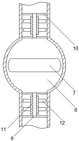
[0020] As an improvement of the present invention, such as figure 2 As shown, among the first flow guide pipe 3 and the second flow guide pipe 4, the front end and the rear end of the powder adding area 8 are respectively provided with turbulence devices, which include along the first flow guide pipe 3 and The spoiler shaft 9 extending axially in the second guide duct 4, the spoiler shaft 9 is connected to the inner walls of the first guide duct 3 and the second guide duct 4 through a plurality of support rods 10, the spoiler shaft 9 A spoiler bushing 11 is arranged on it, and a plurality of spoiler vanes 12 are arranged on the spoiler bushing 11 . By adopting the above-mentioned technical solution, the turbulence device can be arranged so that the mud can be turbulent and agitated during the transportation process, thereby further improving the accuracy of adding the solidifying agent powder.

[0021] The remaining features and advantages of this embodiment are the same as ...


PUM


Abstract

The invention discloses sludge stirring equipment adopting circulation type stirring processing. The sludge stirring equipment comprises a first processing chamber and a second processing chamber, wherein a first stream guidance pipeline is arranged above the first processing chamber; a second stream guidance pipeline is arranged between the first processing chamber and the second processing chamber; stream guidance pumps are respectively arranged in the first stream guidance pipeline and the second stream guidance pipeline; a powder adding device is respectively arranged in the first stream guidance pipeline and the second stream guidance pipeline and comprises a powder adding groove and a powder adding sprayer. The sludge stirring equipment which adopts circulation type stirring processing adopts circulation stirring formed by the sludge at the outer part of the equipment to replace traditional rotary stirring processing to improve equipment operation stability in a stirring process and noise influence on surroundings; meanwhile, according to the stirring way, sludge on any position can flow so as to improve the stirring evenness of the sludge.

Description

technical field [0001] The invention relates to the field of geological engineering, in particular to a sludge stirring device adopting circulation stirring treatment. Background technique [0002] In the preparation process of solidified soil using sludge, it is necessary to stir the sludge to make the uniformity of the sludge meet the processing requirements, and add a curing agent to the sludge during the stirring process to make the sludge easy to process into consolidated soil. Existing mixing equipment often uses traditional rotating blades for mixing treatment. During the actual treatment process, the equipment is often damaged due to repeated impacts between the mixing blades and the sludge, and at the same time, it causes problems such as excessive equipment noise. In addition, due to the certain viscosity of the sludge, it is difficult to ensure a uniform mixing process during the stirring process, and it is also difficult to ensure a uniform powder addition proces...

Claims


Application Information

Patent Timeline
IPC IPC(8): C02F11/00B01F13/10
CPCC02F11/008C02F2301/08C02F2301/046B01F33/811
Inventor 钟天雪
Owner JIANGSU NATURE WAY TECH
Learn More