Industrial robot gripper

A technology of industrial robots and grippers, applied in the direction of chucks, manipulators, manufacturing tools, etc., can solve the problems of small finger opening and closing range, low grasping efficiency, complex structure, etc., and achieve compact structure, light weight, and easy opening and closing wide range of effects

Inactive Publication Date: 2017-09-29
FOSHAN JIANJINJIAN ELECTRONICS TECH CO LTD
View PDF5 Cites 1 Cited by
  • Summary
  • Abstract
  • Description
  • Claims
  • Application Information

AI Technical Summary

Problems solved by technology

[0004] The end clamps of industrial robots generally have the disadvantages of complex structure, small opening and closing range of fingers, heavy weight, and low grasping efficiency

Method used


Image

  • Industrial robot gripper
  • Industrial robot gripper

Examples


Embodiment Construction

[0017] In order to more clearly illustrate the technical solutions in the embodiments of the present invention or the prior art, the following will briefly introduce the drawings that need to be used in the description of the embodiments or the prior art. Obviously, the accompanying drawings in the following description are only These are some embodiments of the present invention. For those skilled in the art, other drawings can also be obtained according to these drawings without any creative effort.

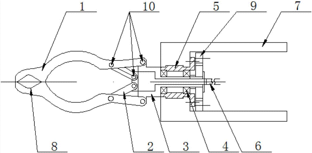
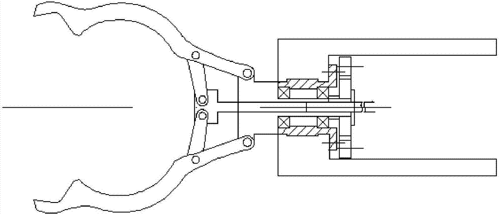
[0018] see as figure 1 —— figure 2 As shown, this specific embodiment adopts the following technical scheme: it includes finger 1, small pull rod 2, bracket 3, bearing 4, sleeve 5, large pull rod 6, U frame 7, clamping port 8, baffle plate 9, pin shaft 10. The two fingers 1 are connected to the side wall of the bracket 3 through the pin shaft 10, one end of the small pull rod 2 is connected to the large pull rod 6 through the pin shaft 10, and the other end of the small pull ...


PUM


Abstract

The invention discloses an industrial robot gripper and relates to the technical field of industrial robots. The industrial robot gripper comprises fingers, a small pulling rod, a support, a bearing, a sleeve, a large pulling rod, a U-shaped frame, clamping openings, a baffle and pin shafts. The two fingers are connected with the side wall of the support through the corresponding pin shafts; one end of the small pulling rod is connected with the large pulling rod through the corresponding pin shaft, and the other end of the small pulling rod is connected with the fingers through the corresponding pin shafts; the large pulling rod is inserted into the support; the support is connected with the U-shaped frame; the sleeve is arranged between the large pulling rod and the U-shaped frame; the bearing is arranged in the sleeve; the clamping openings are formed in the inner sides of the two fingers; and the baffle is arranged on one side of the sleeve. The industrial robot gripper is large in open-close range, compact in structure, small in weight, high in efficiency and capable of fully guaranteeing rigidity and strength and has the advantages of simple structure, reasonable arrangement, low manufacturing cost and the like.

Description

technical field [0001] The invention relates to the technical field of industrial robots, in particular to an industrial robot gripper. Background technique [0002] When the robot is performing operations, a certain device must be installed at the end of the robot's wrist. This assembly is used to directly complete the task. Jobs are successfully performed when the actions of such a device, known as an end effector, also known as a robotic gripper, are coordinated with the movements of the robot's wrist and arm. [0003] In the robot assembly system, the design of the end of the manipulator is very important to reduce the error and cycle time. Since this part is in direct contact with the physical environment, usually the working error can be attributed to many aspects, but the problem often occurs in the end fixture. A well-designed gripper at the end of the manipulator can greatly improve the efficiency, improve the reliability of the system, and provide compensation for...

Claims


Application Information

Patent Timeline
Patent Type & Authority Applications(China)
IPC IPC(8): B25J15/08
CPCB25J15/08
Inventor 林建宝
Owner FOSHAN JIANJINJIAN ELECTRONICS TECH CO LTD
Why Eureka
Try Eureka