Fill valve

A technology for filling valves and liquids, applied in the field of filling valves, to achieve the effect of simple structure

Active Publication Date: 2017-09-26
TECE
View PDF6 Cites 0 Cited by
  • Summary
  • Abstract
  • Description
  • Claims
  • Application Information

AI Technical Summary

Problems solved by technology

[0002] The problem with such filling valves is that the inflow of liquid into the filling valve through the throttle is associated with the generation of noise which is easily perceived as disturbance

Method used


Image

  • Fill valve
  • Fill valve
  • Fill valve

Examples


Embodiment Construction

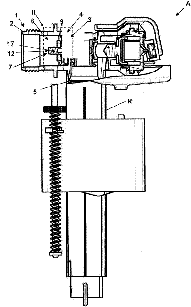
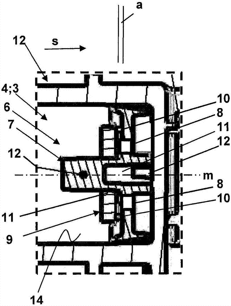
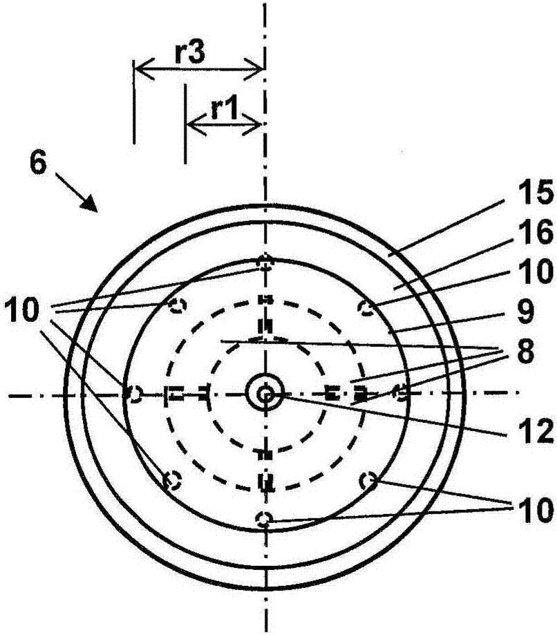
[0057] figure 1shows a side view with a detailed section of a drain device A with a filling valve 1 and a drain line R for installation in a flushing tank not shown here, by means of which drain device A can be Liquid, here water, fills the flushing tank. The filling valve 1 has an inlet 2 with a throttle 4 with a flow regulator 3 for reducing the pressure of the liquid flowing in the direction of flow, and an outlet 5 . figure 2 and 4 show respectively according to figure 1 An enlarged detail of section II of the first embodiment or the second embodiment with the filling valve 1 in . exist image 3 and 5 A respective corresponding top view of the flow regulator 3 is shown in .

[0058] According to the invention, the flow regulator 3 is designed as a volume flow regulating device 6 and achieves a uniform volume flow of the liquid as a function of the flow pressure of the liquid at the inlet 2 . here, figure 2 and 3 A first embodiment of the volume flow regulating d...


PUM


Abstract

The invention relates to a fill valve (1) for filling a tank with a liquid, in particular water, the fill valve (1) having an inlet (2) with a throttle device (4), which has a flow regulator (3), for reducing the pressure of the liquid flowing-in in the direction of flow (s). In order to reduce disturbing noises during filling of a tank, it is proposed that the flow regulator (3) is in the form of a volumetric flow rate regulator (6) for obtaining a volumetric flow rate consistency of the liquid depending on the flow pressure of the liquid at the inlet (2).

Description

technical field [0001] The invention relates to a filling valve for filling a flushing tank with liquid, in particular water, wherein the filling valve has an inlet with a throttle with a flow regulator for reducing the inflow of liquid in the direction of flow pressure. Background technique [0002] A problem with filling valves of this type is that the inflow of liquid into the filling valve through the throttle is associated with the generation of noises which can easily be perceived as disturbances. [0003] A complexly constructed filling valve of this type with a flow regulator is described in EP 1 862 604 A2. Contents of the invention [0004] The object of the present invention is to provide a filling valve of this type which further reduces the flow noise during filling. [0005] The stated object is achieved according to the invention by the features of claim 1 . Advantageous refinements are described in the subclaims. The proposed object is solved in that th...

Claims


Application Information

Patent Timeline
Patent Type & Authority Applications(China)
IPC IPC(8): E03D1/32F16K31/34F16K47/02
CPCE03D1/32F16K31/34F16K47/02G05D7/012
Inventor W·塞德尔
Owner TECE
Why Eureka
Try Eureka