One-touch triangular emergency warning sign

A tripod, push-type technology, used in portable emergency signal devices, optical signals, signal devices, etc., can solve the problems of additional accidents, short visual distance of drivers, danger, etc., to prevent damage from headwinds and prevent 2 times The effect of a rear-end collision

Inactive Publication Date: 2017-09-26
BRING YOU INC
View PDF6 Cites 0 Cited by
  • Summary
  • Abstract
  • Description
  • Claims
  • Application Information

AI Technical Summary

Problems solved by technology

However, in the installation process of the conventional safety tripod, the driver or passenger needs to get out of the car and take out the safety tripod, and then it is necessary to move directly to the installation position and install it in order to comply with the Road Traffic Law.
[0006] As mentioned above, in order to install a safety tripod on the road where the vehicle is running, people's safety cannot be guaranteed when people directly pick up the safety tripod and move to the target position.
[0007] In particular, such as highways, on roads where vehicles are traveling at high speeds, it is necessary to install a safety tripod about 100 meters behind the accident vehicle. However, it is a very dangerous action to pick up a safety tripod and move 100 meters. Drivers will feel panic when they find people walking in the opposite direction in the middle of the road while driving at high speed, which may cause additional accidents
[0008] Moreover, the conventional safety tripod is installed on the ground, because the installation position is the lower part of the driver's field of vision, so it is difficult to observe from a distance, and because of the small safety tripod, it can only be observed at close range, especially when the night is bad In weather conditions, the driver's visibility is extremely short, so the rear driver cannot dodge and thus cannot effectively prevent 2 rear-end collisions

Method used


Image

  • One-touch triangular emergency warning sign
  • One-touch triangular emergency warning sign
  • One-touch triangular emergency warning sign

Examples


Embodiment Construction

[0049] Hereinafter, embodiments of the present invention will be described in detail with reference to the accompanying drawings, so that those skilled in the art of the present invention can easily implement them. However, the present invention can be embodied in various forms, and the present invention is not limited to the embodiments described here. Throughout the specification, the same reference numerals are assigned to similar parts.

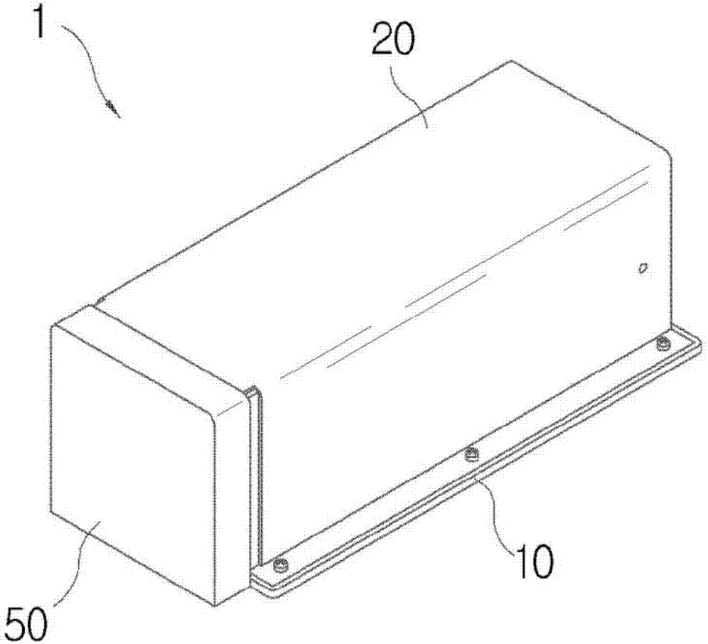
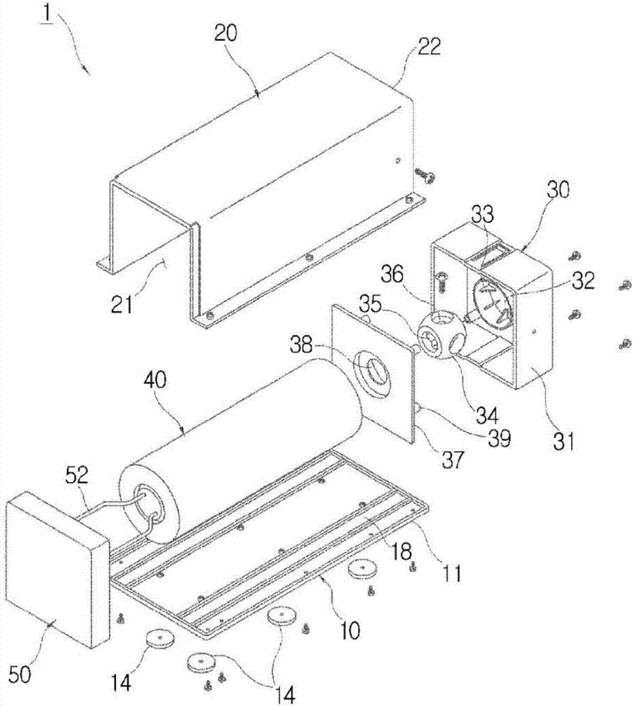
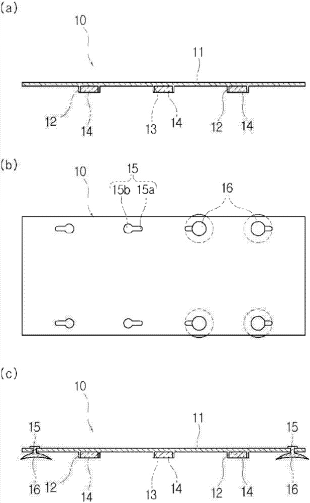
[0050] Hereinafter, the configuration of the present invention will be described with reference to the drawings. figure 1 It is an assembly perspective view showing the push-type mounting tripod of the present invention. figure 2 It is an exploded perspective view showing the push-type safety tripod of the present invention. image 3 Part (a) of image 3 Part (c) is a cross-sectional view showing a horizontal plate constituting the push-type safety tripod of the present invention. Figure 4 It is a cross-sectional view showing the sh...


PUM


Abstract

The present invention relates to a triangular emergency warning sign attached to a vehicle and including a warning sign means for sending a warning sign to the front and rear of the vehicle when an emergency situation occurs. The triangular emergency warning sign comprises: a horizontal plate attachable/detachable to/from the warning sign means; a case provided at the upper part of the horizontal plate and having open rear and lower parts; a front case inserted into the front of the case; a triangular sign device accommodated inside the case and of which the front end is coupled to the front case; and an operating handle provided at the rear of the triangular sign device, and drawing the triangular sign device out or inserting the same thereinto. According to the present invention, the triangular emergency warning sign, which can be easily attached to at least one location among a roof, a bonnet and a trunk of the vehicle when a vehicular emergency situation occurs and can operate a triangular sign part having the warning sign displayed thereon through a simple operation of the operating handle, can be provided and can effectively prevent a secondary rear-end collision of the vehicle.

Description

technical field [0001] The present invention relates to a push-type safety tripod, and in more detail, relates to installing a small warning sign device on the trunk, roof or outside of the vehicle body that will not violate the side lane in the event of an emergency, whereby when an emergency occurs , A push-type safety tripod that accurately transmits warning signs to long-distance rear drivers, thereby preventing secondary rear-end collisions of cars. Background technique [0002] Usually, the car will not only face safety accidents during operation, but also frequent emergency situations that have nothing to do with the driver's intention. It is stipulated that the vehicle must have a push-type safety tripod. [0003] In South Korea recently, large-scale disasters occurred on highways due to not using safety tripods. In the past 3 years, 141 people died due to 2 rear-end accidents on the highway, and the fatality rate reached 61.3%, which is 6 times of 9.7% in ordinary...

Claims


Application Information

Patent Timeline
Patent Type & Authority Applications(China)
IPC IPC(8): B60Q7/00B60Q1/52
CPCB60Q1/52B60Q7/00
Inventor 金源奭
Owner BRING YOU INC
Why Eureka
Try Eureka