Eureka AIR delivers breakthrough ideas for toughest innovation challenges, trusted by R&D personnel around the world.

Fingerprint identification system and intelligent lock

A technology of fingerprint identification and fingerprint information, which is applied in the field of fingerprint combination locks, can solve the problems of many operation steps, and achieve the effect of compact structure

Pending Publication Date: 2017-09-26
浙江王力安防产品有限公司
View PDF6 Cites 10 Cited by
  • Summary
  • Abstract
  • Description
  • Claims
  • Application Information

AI Technical Summary

Problems solved by technology

[0005] Therefore, the technical problem to be solved by the present invention is to overcome the defect that the fingerprint recognition system in the prior art needs to be awakened by pressing a button first when unlocking the smart lock, which leads to many operating steps, thereby providing a fingerprint recognition system and smart lock with easy operation.

Method used


Image

  • Fingerprint identification system and intelligent lock
  • Fingerprint identification system and intelligent lock
  • Fingerprint identification system and intelligent lock

Examples


specific Embodiment approach

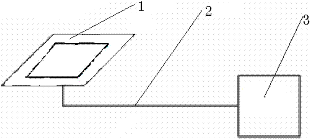
[0040] Such as figure 1 A specific implementation of the shown fingerprint recognition system includes

[0041] The sensing unit includes a collection subunit and a comparison subunit, wherein the collection subunit is used to collect fingerprint information, and the comparison subunit is used to compare the collected fingerprint information with the pre-stored fingerprint information, and judge whether they are consistent, such as the comparison results are consistent , output the power-on command, if the comparison results are inconsistent, no power-on command will be output;

[0042] The execution unit is used to control the unlocking of the door lock when it is powered on;

[0043] The power supply unit is connected to the execution unit respectively, and is used to supply power to the execution unit when receiving the power-on instruction, and cut off the power after the execution unit controls the unlocking of the door lock; When the power-on instruction is executed, t...

Embodiment 2

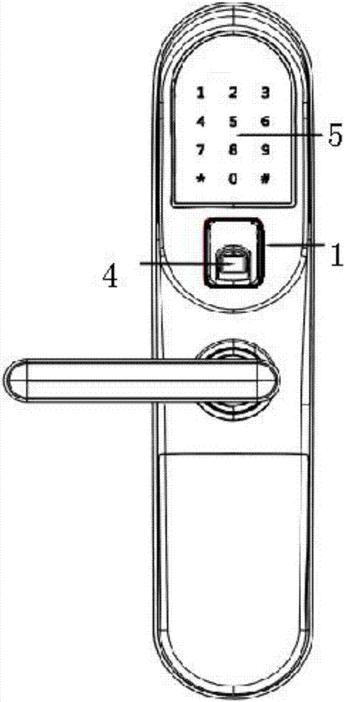
[0055] like image 3 The shown specific implementation of an intelligent lock of the present invention has the fingerprint recognition system provided in Embodiment 1.

[0056] Specifically, the acquisition subunit includes a fingerprint sensor 4, the living finger sensing electrode 1 is a hollow sheet structure, and the living finger sensing electrode 1 is sleeved around the fingerprint sensor 4, and the fingerprint is placed on the sensor The fingerprint information can be collected by the sensor electrode of the living finger, and the structure is compact.

[0057] Specifically, the smart lock also includes a touch screen 5, and unlocking can be realized by inputting a password through the touch screen, thereby realizing diversified unlocking.


PUM


Abstract

The invention provides a fingerprint identification system. The fingerprint identification system comprises an induction unit, an executing unit and a power supply unit, wherein the induction unit comprises an acquisition sub-unit and a comparison sub-unit, the acquisition sub-unit is used for acquiring fingerprint information; the comparison sub-unit is used for comparing the acquired fingerprint information with pre-stored fingerprint information, and judging whether the fingerprint information is consistent or not; if a comparison result is that the fingerprint information is consistent, a power-on instruction is output; if the comparison result is that the fingerprint information is inconsistent, the power-on instruction is not output; the executing unit is used for controlling a door lock to be unlocked when the system is powered on; the power supply unit is connected with the executing unit, and is used for supplying power to the executing unit when receiving the power-on instruction and powering off after the door lock is controlled by the executing unit to be unlocked; when the power-on instruction is not received, the executing unit is powered off; the fingerprint identification system with the structure is provided with the power supply unit, so that the system can enter a low-power-consumption state more rapidly and the aim of saving power is realized.

Description

technical field [0001] The invention relates to the technical field of fingerprint combination locks, in particular to a fingerprint identification system and an intelligent lock. Background technique [0002] With the development of science and technology, anti-theft equipment is becoming more and more technological, and fingerprint code locks have been maturely used on anti-theft doors. [0003] Existing smart locks include a lock front panel, a handle, a fingerprint sensor, and a character button arranged on the lock front panel. When the door lock is locked, the fingerprint identification module is in a low-power standby state. When using the phone, you need to wake up the fingerprint recognition system by pressing a key on the character button, and then press your finger on the fingerprint sensor. If the fingerprint is correct, you can unlock it by turning the handle. [0004] Because the existing smart lock needs to wake up the fingerprint identification system by pre...

Claims


Application Information

Patent Timeline
Patent Type & Authority Applications(China)
IPC IPC(8): G07C9/00G06K9/00
CPCG07C9/00563G06V40/1306G06V40/1365
Inventor 王挺
Owner 浙江王力安防产品有限公司
Why Eureka
Eureka Blog
Learn More