
Touch substrate and driving method, display panel and driving method

A driving method and a technology for touch driving signals, which can be applied to instruments, mechanical mode conversion, computing, etc., and can solve problems such as touch failure

Active Publication Date: 2020-07-03
BOE TECH GRP CO LTD
View PDF8 Cites 0 Cited by
  • Summary
  • Abstract
  • Description
  • Claims
  • Application Information

AI Technical Summary

Problems solved by technology

Since the electrostatic touch layer is closest to the finger, if the mainstream capacitive touch technology is adopted, the electrostatic touch layer will shield the capacitive touch signal, resulting in touch failure

Method used


Image

  • Touch substrate and driving method, display panel and driving method
  • Touch substrate and driving method, display panel and driving method
  • Touch substrate and driving method, display panel and driving method

Examples


Embodiment 1

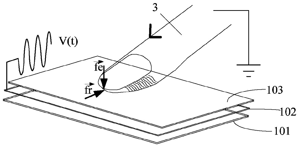
[0043] This embodiment aims at the problem that the experience of pressing the physical keyboard on the current touch screen will affect the touch effect, and provides a touch substrate, which can generate micro-vibrations on the display surface to simulate different material textures to make the human body feel , while ensuring the touch effect, obtain a better texture and tactile experience of the physical keyboard.

[0044] Such as figure 2 Shown is a cross-sectional view of the touch substrate in this embodiment. The touch substrate 1 includes a control unit 11 and a driving layer 12, a feedback layer 13, and a touch layer 14 that are sequentially stacked, wherein:

[0045] The driving layer 12 is used to receive a touch driving signal or a reference signal;

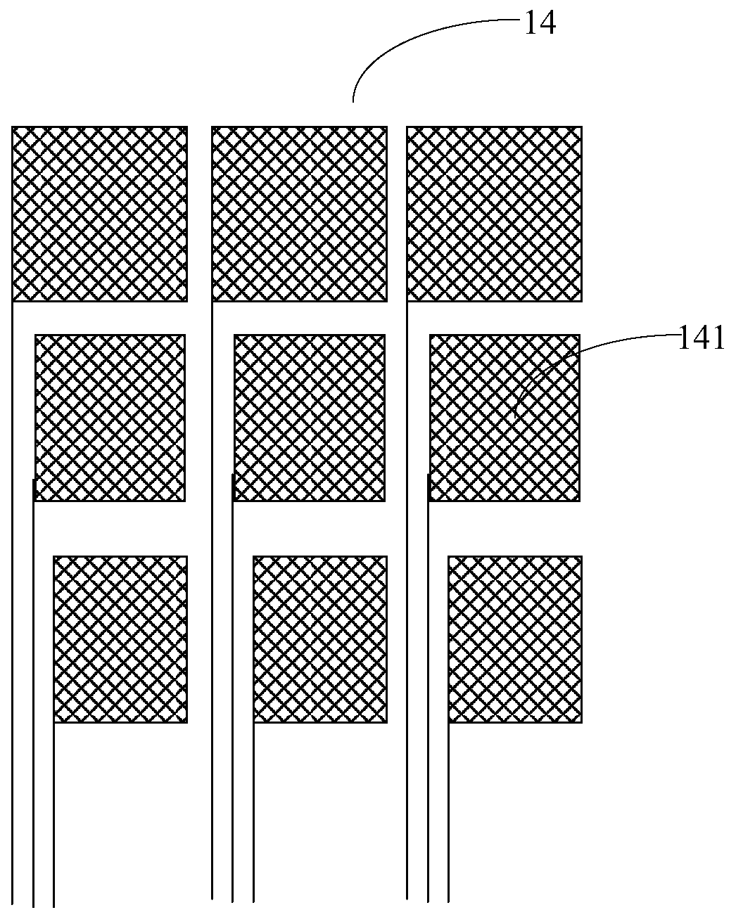
[0046] The touch layer 14 is used to receive touch driving signals or frequency conversion signals, while referring to image 3 , the touch layer 14 includes a plurality of touch sub-electrodes 141 arranged in an ...

Embodiment 2

[0064] This embodiment provides a display panel, which can obtain a better textured touch experience of a physical keyboard while ensuring a touch effect.

[0065] The display panel includes a display substrate, and also includes the touch substrate in Embodiment 1. The touch substrate is disposed on a side of the display substrate close to the display side, where the display substrate can be a liquid crystal display substrate or an organic light emitting diode display substrate. In this way, by setting the touch substrate in the display panel, since the touch substrate includes a feedback layer, the display surface generates micro-vibrations according to the touch signals, so as to simulate different material textures to be felt by the human body.

[0066] In consideration of the device structure and thinning process, for example, for a TN type liquid crystal display substrate, a single incell (single incell, SLIC for short) method is adopted to incorporate a touch function in...


PUM


Abstract

The invention belongs to the field of display technology, and in particular relates to a touch substrate and a driving method, a display panel and a driving method. The touch substrate includes a control unit and a driving layer, a feedback layer and a touch layer arranged in sequence, wherein: the driving layer is used to receive a touch driving signal or a reference signal; the touch layer is used to receive a touch Control drive signal or frequency conversion signal, the touch layer includes a plurality of touch sub-electrodes arranged in an array, the touch sub-electrodes sense touch signals, and the touch signals are transmitted to the control unit; the control unit , used to receive the touch signal, and provide a frequency conversion signal to the touch sub-electrode that generates the touch signal; the feedback layer is in contact with the drive layer and the touch layer respectively, and is used to The frequency conversion signal generates a touch feedback response in the corresponding area of ​​the touch sub-electrode. While maintaining the convenience of touch control, the touch substrate can also obtain a better textured touch experience of a physical keyboard.

Description

technical field [0001] The invention belongs to the field of display technology, and in particular relates to a touch substrate and a driving method, a display panel and a driving method. Background technique [0002] With the development of science and technology, flat panel display devices LCD (Liquid Crystal Display: Liquid Crystal Display) and OLED (Organic Light-Emitting Diode: Organic Light-Emitting Diode) display devices have realized touch control. [0003] Although the touch screen of smart devices has brought many new experiences to users, it is convenient and fast, on the one hand, it causes people to lose the experience of pressing the physical keyboard, and on the other hand, people have a strong demand for touch experience. After all, tactile feedback (Touch feedback) can increase people's experience of using the touch screen to a certain extent. When people touch the screen, they feel the experience of touching a real object. For example, when playing an Angr...

Claims


Application Information

Patent Timeline
Patent Type & Authority Patents(China)
IPC IPC(8): G06F3/01G06F3/044
CPCG06F3/016G06F3/044G06F3/0443G06F3/0412G06F3/0416G06F2203/014G06F3/0488G02F1/13338
Inventor 丁小梁王海生刘英明王鹏鹏韩艳玲
Owner BOE TECH GRP CO LTD
Learn More