A beacon layout and image processing method based on UAV pose calculation

An image processing and unmanned aerial vehicle technology, applied in image data processing, computing, image analysis, etc., can solve the problem that the design conditions of cooperative beacons are not strict enough, there is no suitable method for cooperative beacon detection, extraction and matching, and no consideration is given to The influence of beacon pose calculation and other issues

Active Publication Date: 2018-08-07
徐泽宇 +1
View PDF6 Cites 2 Cited by
  • Summary
  • Abstract
  • Description
  • Claims
  • Application Information

AI Technical Summary

Problems solved by technology

At present, most visual landing navigation systems are based on image processing technology in the visible light range, and there are many factors that affect visible light imaging in nature. In addition, landing at night is also a difficulty for visible light visual landing navigation systems
[0004] At present, in the research of visual landing guidance technology at home and abroad, the design conditions for cooperative beacons are not strict enough, and most of them are limited to ensuring visibility. The research on non-visible infrared beacons also mostly stays on heating metals.
In addition, in the process of visual landing guidance under long-distance and large-scale transformation, the influence of beacon design on pose calculation is not considered
At the same time, there are many methods for the detection, extraction and matching of cooperative beacon feature points at home and abroad, but there is still no suitable method for the detection, extraction and matching of cooperative beacons with a specific structure.
For the pose calculation algorithm, the research on it at home and abroad is also very rich, but there is no good analysis on how to choose the pose calculation algorithm in practical engineering problems

Method used


Image

  • A beacon layout and image processing method based on UAV pose calculation
  • A beacon layout and image processing method based on UAV pose calculation
  • A beacon layout and image processing method based on UAV pose calculation

Examples


Embodiment Construction

[0177] The present invention is further described below in conjunction with embodiment, but the present invention is not limited to following embodiment:

[0178] 1 Beacon Design

[0179] The visual guidance system designed in this scheme satisfies the guidance conditions shown in Table 1:

[0180] Table 1 Guidance conditions of visual guidance system

[0181]

[0182] In addition, the update rate of position data during the landing process is 12HZ. To meet these requirements, it is necessary to select equipment through correlation analysis with imaging, measurement and calculation. Firstly, the imaging equipment is selected by calculating the required image imaging accuracy, and then the layout constraints of ground beacons are designed by analyzing the imaging changes during the landing process.

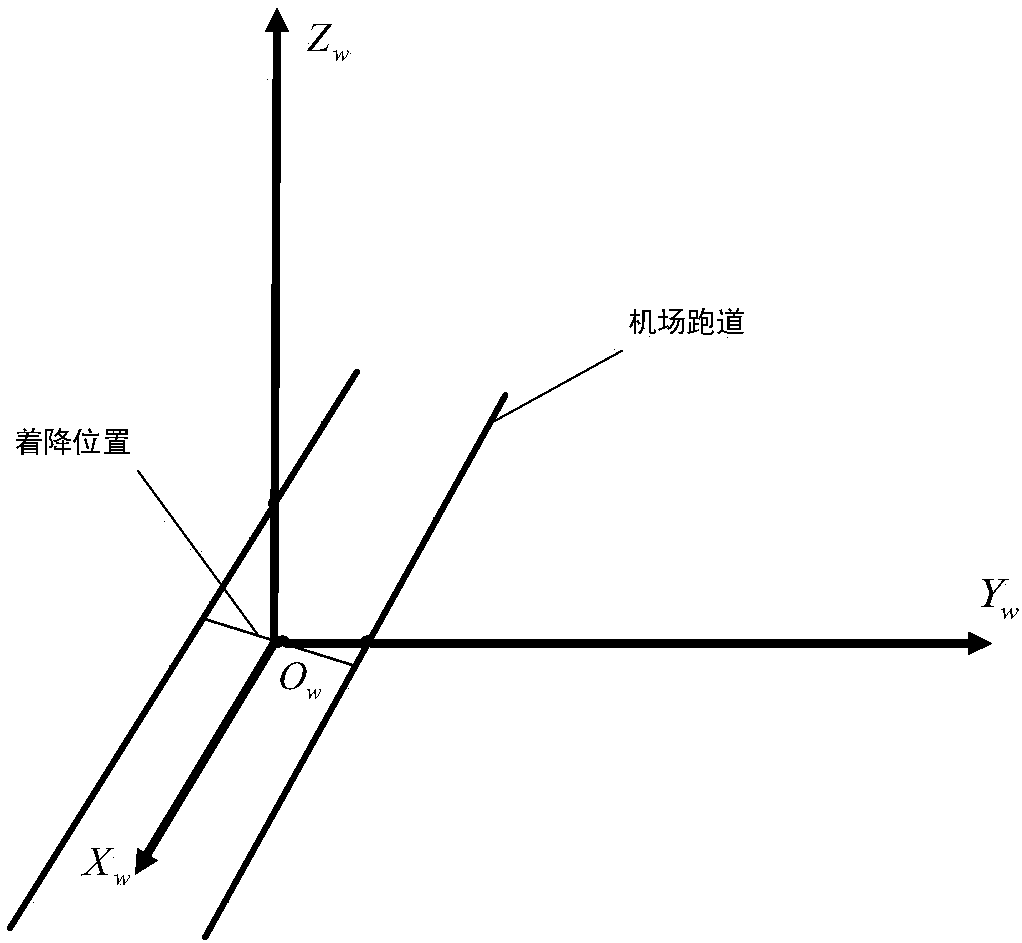
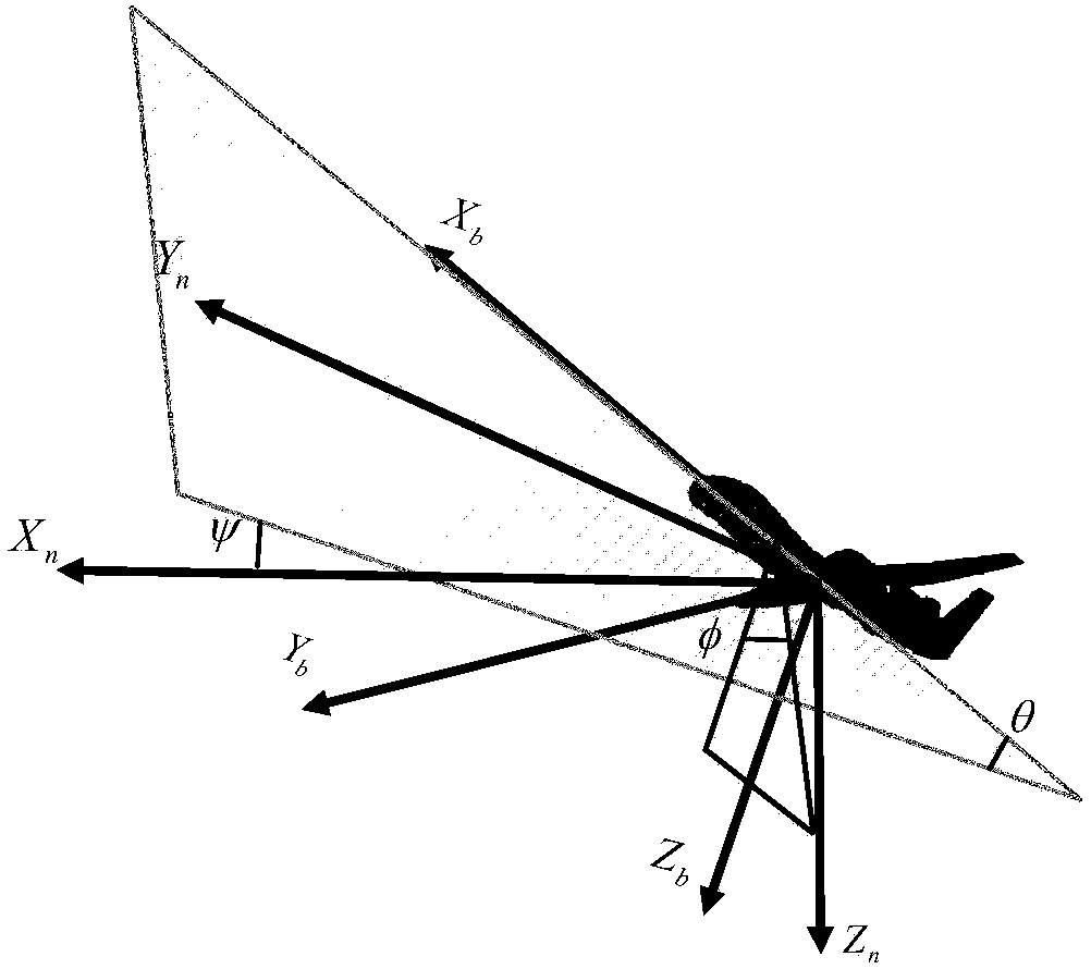
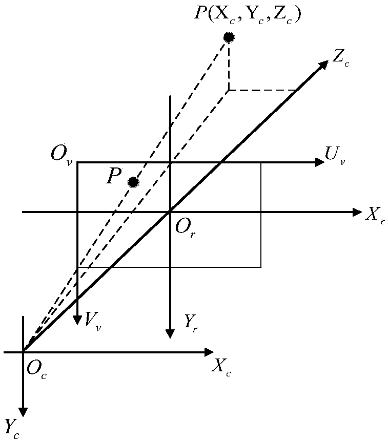
[0183] Definition of coordinate system and aircraft attitude angle

[0184] For the convenience of description and calculation, the coordinate systems defined in this scheme ...


PUM


Abstract

A beacon layout and image processing method based on UAV pose calculation. Firstly, the machine vision-guided landing of UAV is designed. According to the built visual imaging system, the image sensitivity is ensured and the field of view distortion is analyzed. Under certain conditions, combined with the possible poses during the landing process, design the beacon structure and layout method required for the vision-guided landing. Then, according to the designed vision-guided system, for different cooperative beacon configurations, three measures are proposed. The index of algorithm applicability is used to evaluate and screen the pose calculation algorithm. Finally, the ground cooperation beacon used is infrared LED. The imaging effect of infrared LED is more stable, the imaging distance is longer, and the imaging accuracy is higher. This method is simple and easy to implement, has low requirements on the configuration of the landing site, is more convenient and faster to extract features from near-infrared images, expands the scope of application of the vision system, and can detect and identify all-weather and all-weather; Machine attitude information.

Description

technical field [0001] The invention relates to beacon position confirmation when a UAV lands, in particular to a beacon arrangement and image processing method based on UAV pose calculation. Background technique [0002] Unmanned Aerial Vehicles (UAVs) have received widespread attention since their inception. With the advancement of science and technology, UAVs have been applied to many aspects such as terrain detection, disaster detection, and aerial reconnaissance. The UAV landing stage is the stage with the highest accident rate in UAV missions. Therefore, research on safe and reliable automatic landing guidance methods is very important for ensuring the safety of UAVs, reducing the accident rate, effectively completing combat tasks, and reducing the cost of UAV use. Waiting is of great significance. Seeking a simple, fast, autonomous, and reliable UAV landing guidance method is an important problem that needs to be solved at present. [0003] Compared with the traditi...

Claims


Application Information

Patent Timeline
Patent Type & Authority Patents(China)
IPC IPC(8): G01S11/12G01C11/34G06T7/11G06T7/136G06T7/73
CPCG01C11/34G01S11/12G06T7/11G06T7/136G06T7/73G05D1/0676
Inventor 徐泽宇姚顺李沅澔
Owner 徐泽宇
Why Eureka
Try Eureka