
Multi-functional power equipment cabinet with multiple damping functions

A multi-functional technology for power equipment, applied in anti-seismic equipment, electrical components, substation/power distribution device shells, etc., can solve the problems that the locking effect of the locking device is difficult to meet the requirements, the power cabinet is bulky, and the heat dissipation efficiency is low. Unstable work and inconvenient movement, uniform and effective heat dissipation, and the effect of ensuring normal operation

Inactive Publication Date: 2017-09-22
HEFEI ANLI ELECTRIC POWER ENG CO LTD
View PDF4 Cites 18 Cited by
  • Summary
  • Abstract
  • Description
  • Claims
  • Application Information

AI Technical Summary

Problems solved by technology

[0003] As we all know, power equipment will generate a lot of heat when it is working. If the heat cannot be dissipated in time, it will accumulate in the power equipment cabinet, which will lead to a fire in severe cases. To cool down and dissipate heat, but its heat dissipation efficiency is low and cannot meet the requirements, and it is still relatively harmful; in addition, power equipment needs to have a certain shock absorption capacity to cope with earthquakes or extreme windy weather, and the existing power The cabinet obviously does not meet such requirements; the power cabinet is relatively heavy and needs to be carried out by lifting equipment when moving, which is very inconvenient to move. In the prior art, there are also rollers installed at the bottom, and locking devices are set on the rollers, but the locking device The locking effect is still difficult to meet the requirements, causing the cabinet body of the power cabinet to shake easily when in use

Method used


Image

  • Multi-functional power equipment cabinet with multiple damping functions
  • Multi-functional power equipment cabinet with multiple damping functions
  • Multi-functional power equipment cabinet with multiple damping functions

Examples


Embodiment Construction

[0025] The following will clearly and completely describe the technical solutions in the embodiments of the present invention with reference to the accompanying drawings in the embodiments of the present invention. Obviously, the described embodiments are only some of the embodiments of the present invention, not all of them. Based on the embodiments of the present invention, all other embodiments obtained by persons of ordinary skill in the art without making creative efforts belong to the protection scope of the present invention.

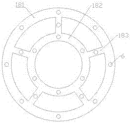
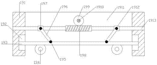
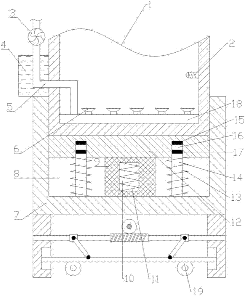
[0026] Such as Figure 1-3 As mentioned above, in the embodiment of the present invention, a multifunctional power equipment cabinet with multiple shock absorption functions includes a cabinet body 1, and the bottom of the cabinet body 1 is provided with an air distribution pipe 18, and the air distribution pipe 18 is connected to the outside world. The air pipes 5 are connected, and the air inlet pipe 5 is evenly provided with a number of air ou...


PUM


Abstract

The invention discloses a multi-functional power equipment cabinet with multiple damping functions. The multi-functional power equipment cabinet comprises a cabinet body. The bottom of the cabinet body is provided with an air distribution tube that is communicated with an external air inlet tube. A plurality of air outlets are uniformly arranged on the air inlet tube. The outer side wall of the cabinet body is provided with a cooling liquid box. The air inlet tube penetrates through the cooling liquid box. The air inlet tube is provided with an induced draft fan. The inner side wall of the cabinet body is provided with a temperature sensor. The temperature sensor and the induced draft fan are electrically connected with a control device. A base is arranged below the cabinet body. The base is provided with a first groove. The bottom of the first groove is provided with a first rubber damping block. The first rubber damping block is internally provided with a cavity. The air distribution tube can distribute cold wind into the cabinet body uniformly, so as to dissipate heat of the cabinet body uniformly and effectively to ensure power equipment in the cabinet body to run normally; further the temperature sensor can reduce the temperature of the interior of the cabinet body intelligently.

Description

technical field [0001] The invention relates to the technical field of power equipment cabinets, in particular to a multi-functional power equipment cabinet with multiple damping functions. Background technique [0002] Power equipment cabinets (boxes) are divided into power cabinets (boxes), lighting cabinets (boxes), and metering cabinets (boxes), which are the final equipment of the power distribution system. The power equipment cabinet is a general term for the motor control center. The power equipment cabinet is used in the occasions where the load is relatively scattered and there are few circuits; the motor control center is used in the occasions where the load is concentrated and there are many circuits. They distribute the electric energy of a certain circuit of the upper-level power equipment to the nearest load. This level of equipment shall provide protection, monitoring and control of the load. [0003] As we all know, power equipment will generate a lot of h...

Claims


Application Information

Patent Timeline
IPC IPC(8): H02B1/56H02B1/54H02B1/30
CPCH02B1/565H02B1/303H02B1/54
Inventor 殷世尧
Owner HEFEI ANLI ELECTRIC POWER ENG CO LTD
Learn More