Sharing Charge Pal leasing cabinet
A charging treasure and rental cabinet technology, which is applied in the field of shared charging treasure rental equipment, to achieve the effects of improving rental efficiency, ensuring safety, and improving utilization
- Summary
- Abstract
- Description
- Claims
- Application Information
AI Technical Summary
Problems solved by technology
Method used
Image
Examples
Embodiment 1
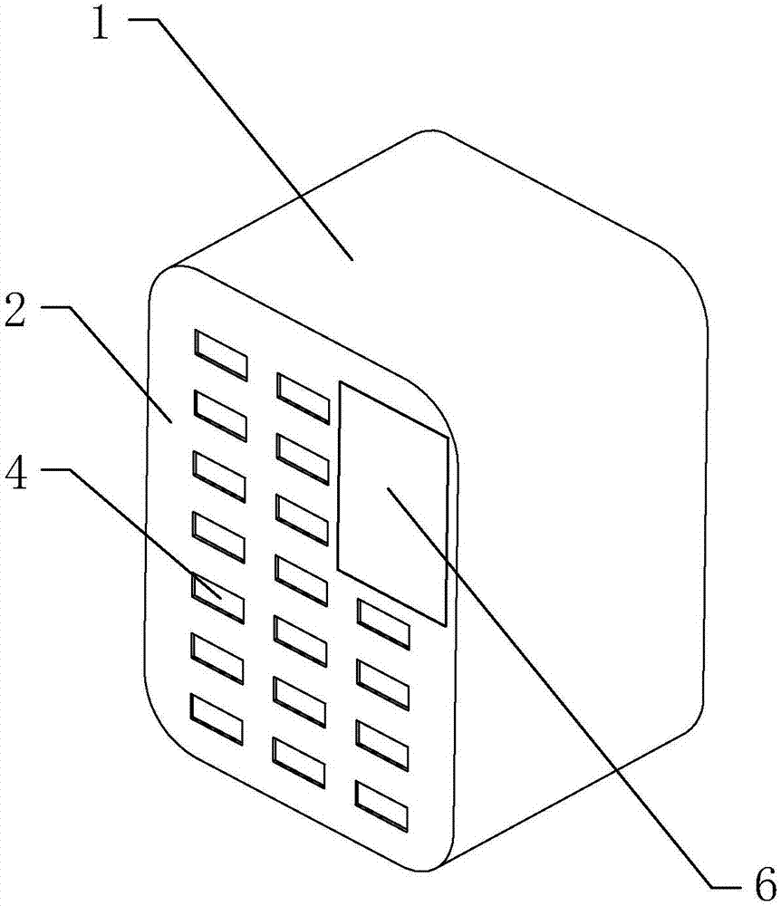
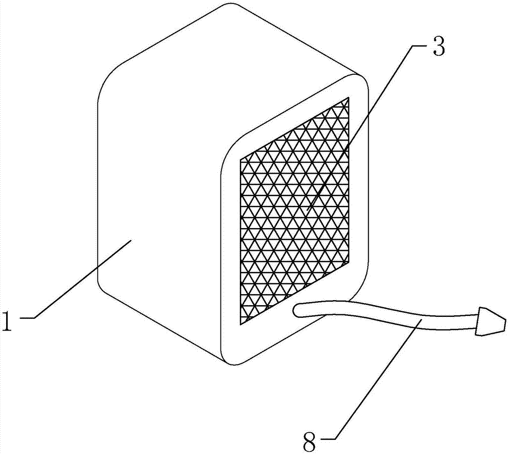
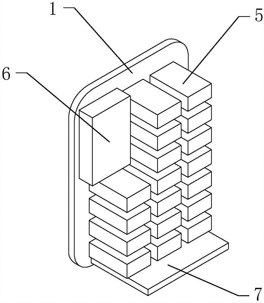
[0042] see Figure 1-7 , a shared charging treasure rental cabinet, including a cabinet body 1, the cabinet body 1 is provided with a front panel 2 and a rear panel 3, the front panel 2 is provided with a charging treasure inlet and outlet 4, and the front panel 2 and the The display 6 is fixedly connected, the front panel 2 is fixedly connected with the shell 501 provided on the charging treasure storage part 5, the charging treasure inlet and outlet 4 is aligned with the charging treasure storage part 5, and a circuit board is arranged inside the cabinet 1 7. The circuit board 7 is arranged under the power bank storage part 5, the circuit board 7 is electrically connected to the power cord 8, the power cord 8 extends out of the cabinet body 1, and the power bank storage part 5 is controlled by the shell 501, storage compartment 502, partition 503, charging throne 504, guide rail 505, placement slot 506, front baffle 507, rear baffle 508, light sensor 509, USB port 510, elect...
Embodiment 2
[0045] combine Figure 8 to Figure 12 As shown, this embodiment makes the following improvements on the basis of Embodiment 1: a password input device 9 is installed on the front panel below the display. When the present invention is used for the first time, the password is set through the password input device. When the password is used for the second time, the power bank can be rented directly by inputting the password through the password input device. The problem of not being able to scan the code.
[0046] The password input device includes a first housing 91, a second housing 92 and a cover plate 93 connected in sequence; a finger insertion port 912 through the front and back is formed on the first housing, An installation cavity 914 is formed on the left side of the finger insertion opening, and a first installation opening 913 is formed on the front side of the first housing corresponding to the installation cavity, and a connecting wall 911 is formed on the outer per...
PUM
 Abstract
Description
Claims
Application Information
 - R&D Engineer
- R&D Manager
- IP Professional
- Industry Leading Data Capabilities
- Powerful AI technology
- Patent DNA Extraction
Browse by: Latest US Patents, China's latest patents, Technical Efficacy Thesaurus, Application Domain, Technology Topic, Popular Technical Reports.
© 2024 PatSnap. All rights reserved.Legal|Privacy policy|Modern Slavery Act Transparency Statement|Sitemap|About US| Contact US: help@patsnap.com


