
Computer dust removal device

A technology of dust removal device and computer, applied in calculation, separation method, instrument and other directions, can solve the problems of reduced machine operation efficiency, narrow space, inconvenient dust removal, etc., and achieve the effect of small pressure loss, large air flow, and not easy to block.

Inactive Publication Date: 2020-02-07
SHANDONG JIAOTONG UNIV
View PDF8 Cites 0 Cited by
  • Summary
  • Abstract
  • Description
  • Claims
  • Application Information

AI Technical Summary

Problems solved by technology

[0002] For the convenience of heat dissipation, the chassis shell will be equipped with heat dissipation holes and cooling fans to drive air flow to dissipate heat inside the chassis shell. Due to the dust particles in the air, there will be a lot of dust inside the chassis if it is not cleaned in time, which will cause the machine to The operating efficiency drops, and sometimes it even leads to poor contact of the graphics card, memory card and other plug-in components. However, due to the small internal space of the machine, it is inconvenient to remove dust, so the chassis needs to be disassembled. , sweep with a brush, it is not easy to clean due to long-term accumulation of dust
It is difficult to master the force. If the force is too small, the dust will not be cleaned thoroughly. If you use more force, although it can achieve a good dust cleaning effect, it is easy to damage the circuit in the chassis and cause damage to the circuit.

Method used


Image

  • Computer dust removal device
  • Computer dust removal device
  • Computer dust removal device

Examples


Embodiment

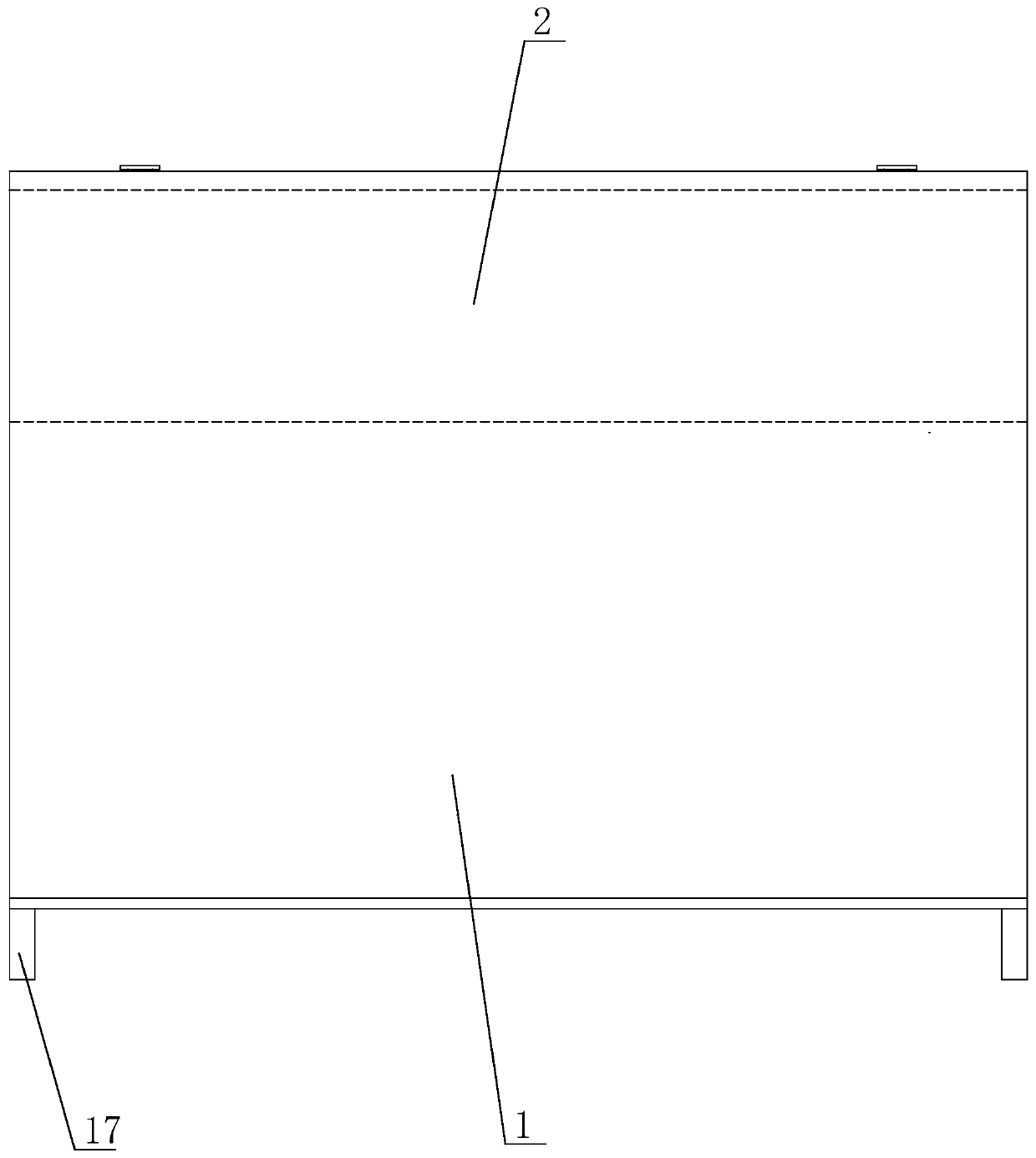
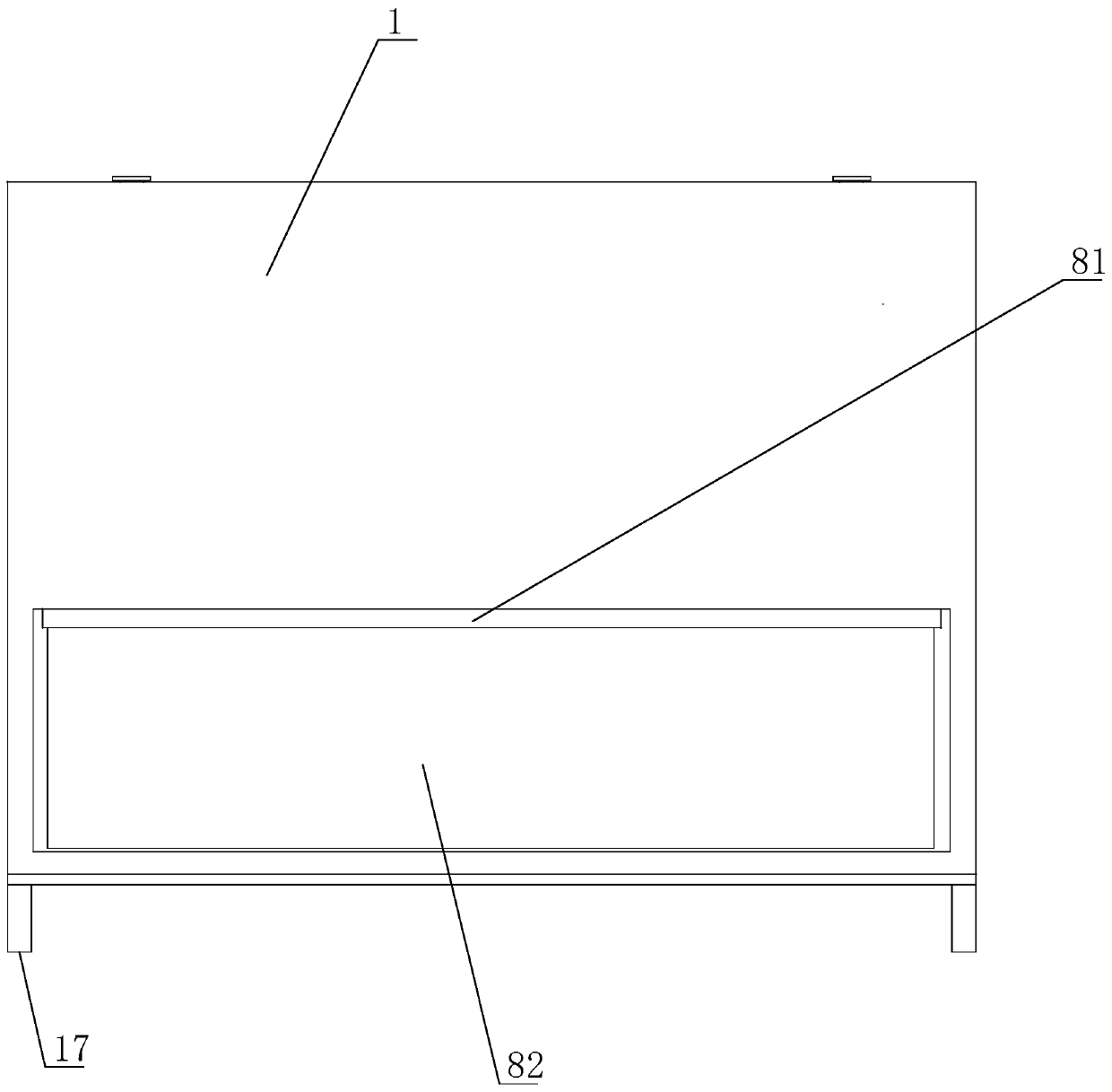
[0040] The computer dust removal device includes a case shell 1, and a moisture-proof support seat 17 is arranged at the bottom of the case shell 1. One side of the top of the chassis shell 1 is provided with a rectangular first through hole 2, and a first support frame 3 adapted to the cavity of the first through hole 2 is arranged in the first through hole 2, and the first support frame 3 is provided with a filter membrane 4, and the filter membrane 4 is made of one or more filter materials in machine-made cloth, non-woven fabric and glass fiber. The left and right sides of the first supporting frame 3 are all vertically provided with a first chute 31, the upper and lower ends of the first chute 31 are provided with a slide bar 32, and the two slide bars 32 are connected by a spring 33, The end of the slide bar 32 away from the spring 33 protrudes from the first support frame 3 , and a slot matching with the slide bar 32 is provided on the chassis shell 1 , and the slide bar...


PUM


Abstract

The invention discloses a computer de-dusting apparatus. The computer de-dusting apparatus comprises a case shell; a first rectangular through hole is formed in one side of the top end of the case shell; a first support frame is arranged in the first through hole; a filter membrane is arranged in the first support frame; the first support frame is provided with sliding rods; transverse rods are arranged at two ends, oppositely located on the first support frame, of each sliding rod; a second support frame is arranged at one end, far away from the first support frame, of each transverse rod; a first metal wire mesh is arranged in each second support frame; a shell body is arranged at the lower part, oppositely located on the first through hole, of the case shell; a power apparatus for driving gas to flow is arranged in the shell body; a groove is formed in the bottom end of one side, far away from the first through hole, of the case shell body; the groove is connected with the case shell body through a plurality of first air outlet through holes; a fixed seat is arranged at the top end of the groove; and a dustproof membrane is arranged on the fixed seat. The computer de-dusting apparatus has the beneficial effects that the case shell can be efficiently cooled and dust particles in air entering the case shell can be removed.

Description

technical field [0001] The invention mainly relates to the field of computer dust removal, in particular to a computer dust removal device. Background technique [0002] For the convenience of heat dissipation, the chassis shell will be equipped with heat dissipation holes and cooling fans to drive air flow to dissipate heat inside the chassis shell. Due to the dust particles in the air, there will be a lot of dust inside the chassis if it is not cleaned in time, which will cause the machine to The operating efficiency drops, and sometimes it even leads to poor contact of the graphics card, memory card and other plug-in components. However, due to the small internal space of the machine, it is inconvenient to remove dust, so the chassis needs to be disassembled. , Sweep with a brush, it is not easy to clean due to long-term accumulation of dust. It is difficult to master the force. If the force is too small, the dust will not be cleaned thoroughly. If the force is greater, ...

Claims


Application Information

Patent Timeline
Patent Type & Authority Patents(China)
IPC IPC(8): G06F1/18G06F1/20B01D46/12B01D46/54
CPCB01D46/12B01D46/543G06F1/182G06F1/20
Inventor 张开文
Owner SHANDONG JIAOTONG UNIV
Learn More