
N*N optical switch matrix capable of inhibiting crosstalk and signal transmission method of matrix

A technology of optical switch matrix and optical switch, which is applied in the field of optical communication, can solve the problems of rising device cost, not being ideal, and increasing control complexity, etc., and achieve the effect of small control complexity, strong uniformity, and simple process

Active Publication Date: 2017-09-22
CHINA ELECTRONICS TECH GRP NO 23 RES INST
View PDF2 Cites 5 Cited by
  • Summary
  • Abstract
  • Description
  • Claims
  • Application Information

AI Technical Summary

Problems solved by technology

The disadvantages are: limited by the physical properties of the device, it is not ideal, the cost of the device increases, and the complexity of control increases, which is not conducive to the realization of large-scale cascaded optical switch arrays
The disadvantage is that although the network topology and the characteristics of the DWDM system are comprehensively considered, the complexity of the network nodes and the increase in the number of passive devices increase the cost of a single network node, which is also not conducive to large-scale cascaded optical switches. Implementation of the matrix

Method used


Image

  • N*N optical switch matrix capable of inhibiting crosstalk and signal transmission method of matrix
  • N*N optical switch matrix capable of inhibiting crosstalk and signal transmission method of matrix
  • N*N optical switch matrix capable of inhibiting crosstalk and signal transmission method of matrix

Examples


Embodiment Construction

[0044] In order to make the purpose, technical solutions and advantages of the present invention clearer, the present invention will be described in further detail below in conjunction with the accompanying drawings and embodiments. It should be understood that the specific embodiments described here are only used to explain the present invention and are not intended to limit the invention.

[0045] Reference will now be made in detail to embodiments of the invention, examples of which are illustrated in the accompanying drawings. The suffixes "module" and "unit" of elements are used here for convenience of description, and thus may be used interchangeably without any distinguishable meaning or function.

[0046] Although all elements or units constituting an embodiment of the present invention are described as being incorporated into a single element or operated as a single element or unit, the present invention is not necessarily limited to such an embodiment. According to ...


PUM


Abstract

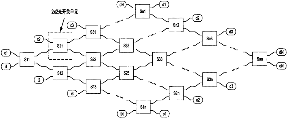
The invention relates to an N*N optical switch matrix capable of inhibiting crosstalk and a signal transmission method of the matrix. The optical switch matrix comprises N input ends, N output ends and N2 optical switch units, the N2 optical switch units are positioned between the N input ends and the N output ends, and are connected in a crossed manner, and the initial state of each optical switch unit is set as a crossed transmission state; and when it is required to connected the ith input end with the jth output end in the optical switch matrix, the (j,i)th optical switch unit in the matrix is set as a straight-through transmission state, and all other optical switch units in the ith row and the jth column in the optical switch matrix are kept in the crossed transmission state.

Description

technical field [0001] The invention relates to the technical field of optical communication, in particular to an electro-optical silicon-based waveguide N*N optical switch matrix with crosstalk suppression and a signal transmission method thereof. Background technique [0002] At present, there are many technical approaches for the realization of optical switches, one of which is typical interferometric optical switch technology. Electro-optic silicon-based waveguide optical switch is a typical interferometric optical switch that uses the plasma dispersion effect of silicon to modulate the refractive index. Compared with other optical switch technologies, the switch has outstanding advantages. However, while using the plasmonic dispersion effect of silicon to modulate the refractive index of silicon, it will be accompanied by parasitic absorption loss. The optical power in the optical switch is no longer maintained equal, and there is always a situation where the "off" sta...

Claims


Application Information

Patent Timeline
Patent Type & Authority Applications(China)
IPC IPC(8): G02B6/35
CPCG02B6/3546
Inventor 严亭李冰
Owner CHINA ELECTRONICS TECH GRP NO 23 RES INST
Learn More