
A method of transmitting and receiving mimo-sar signals based on space-time coding

A technology of signal transmission and space-time coding, which is applied in the field of MIMO-SAR signal transmission and reception, can solve problems such as violations, and achieve the effect of eliminating crosstalk between channels

Active Publication Date: 2016-04-06
NAT UNIV OF DEFENSE TECH
View PDF4 Cites 0 Cited by
  • Summary
  • Abstract
  • Description
  • Claims
  • Application Information

AI Technical Summary

Problems solved by technology

But the price is to use two PRI (pulserepetitioninterval, pulse repetition period) in the slow time to realize two ATIs of Alamouti space-time coding at the transmitting end, resulting in doubling of PRF (pulserepetitionfrequency, pulse repetition frequency), which usually violates the use of MIMO The original intention of technology to reduce PRF

Method used


Image

  • A method of transmitting and receiving mimo-sar signals based on space-time coding
  • A method of transmitting and receiving mimo-sar signals based on space-time coding
  • A method of transmitting and receiving mimo-sar signals based on space-time coding

Examples


Embodiment Construction

[0020] The method for transmitting and receiving MIMO-SAR signals based on space-time coding provided by the present invention will be described in detail below in conjunction with the accompanying drawings.

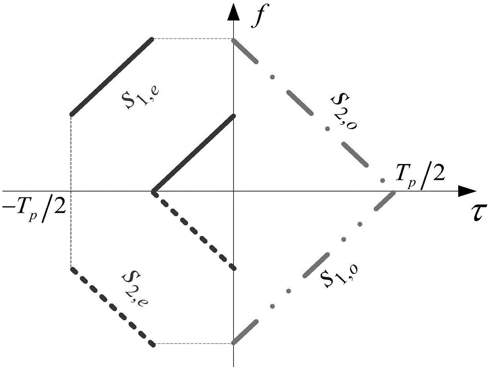
[0021] figure 1 It shows an example of the transmission signal during the signal transmission process of the present invention. The transmission waveform is displayed in the time-frequency domain. The abscissa is time (unit: second), and the ordinate is frequency (unit: Hz). The first transmission channel corresponds to two The emission waveform s of the Alamouti emission cycle 1,e (τ 1 ) and s 1,o (τ 2 ) are represented by a solid line and a two-dot-one-dash line respectively, and the second transmission channel corresponds to the transmission waveform s of two Alamouti transmission cycles 2,e (τ 1 ) and s 2,o (τ 2 ) are represented by a dotted line and a one-dot-dash line, respectively. In this instance T sub The value is . It can be seen from the figure th...


PUM


Abstract

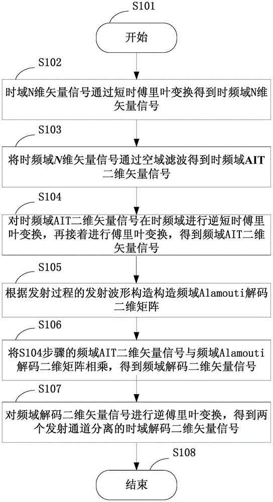
The invention provides an MIMO-SAR signal transmitting and receiving method based on space-time coding. The MIMO-SAR signal transmitting and receiving method is suitable for transmitting and receiving of dual-transmitter multiple-receiver SAR system signals. The technical scheme is that the MIMO-SAR signal transmitting and receiving method comprises: a signal transmitting step, namely the sum of two transmitting periods is integrated to one PRI at the transmitting end; a signal receiving step, namely received time domain N-dimensional vector signals are subjected to spatial filtering to obtain time-frequency domain AIT two-dimensional vector signals; transmitted waveforms are utilized to establish a frequency domain Alamouti decoding two-dimensional matrix; the frequency domain AIT two-dimensional vector signal with the frequency domain Alamouti decoding two-dimensional matrix are multiplied obtain frequency domain decoding two-dimensional vector signal, and then inverse fourier transform is performed to obtain a two-dimensional vector signal with two separated transmitting channel. The MIMO-SAR signal transmitting and receiving method can achieve virtual image inhibition and eliminate inter-channel crosstalk, and meanwhile is suitable for even wide scene distributed target observation and sparse strong-scattering target observation under the weak scattering background.

Description

technical field [0001] The invention belongs to the technical field of radar system design, and more specifically relates to a signal transmitting and receiving method applied to MIMO-SAR (Multiple-Input Multiple-Output Synthetic Aperture Radar). Background technique [0002] MIMO-SAR is a new concept SAR system that comprehensively applies multi-channel technology at the transmitting end and DBF (Digital Beam Forming) technology at the receiving end. It is an important development direction of the new system spaceborne SAR system in the future. By rationally designing multiple waveforms for multi-channel transmission, the advantages of the degree of freedom of the MIMO-SAR system can be more effectively utilized, and it has great potential advantages in significantly improving the performance, flexibility, and adaptability of future SAR systems. Effective separation of echoes from multiple transmit waveforms is the prerequisite for the realization of MIMO-SAR systems, and t...

Claims


Application Information

Patent Timeline
Patent Type & Authority Patents(China)
IPC IPC(8): G01S7/28
CPCG01S13/003G01S13/90H04L1/0625H04L1/0631G01S13/904
Inventor 何峰董臻孙造宇马喜乐金光虎何志华余安喜黄海风张永胜
Owner NAT UNIV OF DEFENSE TECH
Learn More