Annular micro arc cathode discharge plasma propelling device

A discharge plasma and propulsion device technology, which is applied in the field of micro propulsion devices, can solve the problems of large energy loss of magnetic focusing devices, electromagnetic coil energy loss, and large mass, and achieve the effects of avoiding energy loss, reducing mass, and light weight

Inactive Publication Date: 2017-09-22
BEIJING INST OF CONTROL ENG
View PDF3 Cites 3 Cited by
  • Summary
  • Abstract
  • Description
  • Claims
  • Application Information

AI Technical Summary

Problems solved by technology

[0005] First, the mass is relatively large. Conventional miniature electric propulsion devices, such as miniature Hall propulsion modules, miniature ion propulsion modules and other miniature electric propulsion modules, all need to use special propellant storage tanks, pipelines, valves and other storage and supply devices, resulting in higher quality
[0006] Second, the total impulse is low. The specific impulse of conventional micro-electric propulsion devices is generally about 1000s. Due to the weight limit of micro-nano satellites, the total impulse of conventional micro-electric propulsion devices has a certain limit
[0007] Third, the energy loss of the magnetic focusing device is large. Conventional micro electric propulsion devices use electromagnetic coils to generate magnetic fields to focus and accelerate charged particles, but there will be a certain amount of energy loss during the working process of the electromagnetic coils

Method used


Image

  • Annular micro arc cathode discharge plasma propelling device
  • Annular micro arc cathode discharge plasma propelling device
  • Annular micro arc cathode discharge plasma propelling device

Examples


Embodiment Construction

[0034] The present invention will be further described below in conjunction with accompanying drawing description and specific embodiment:

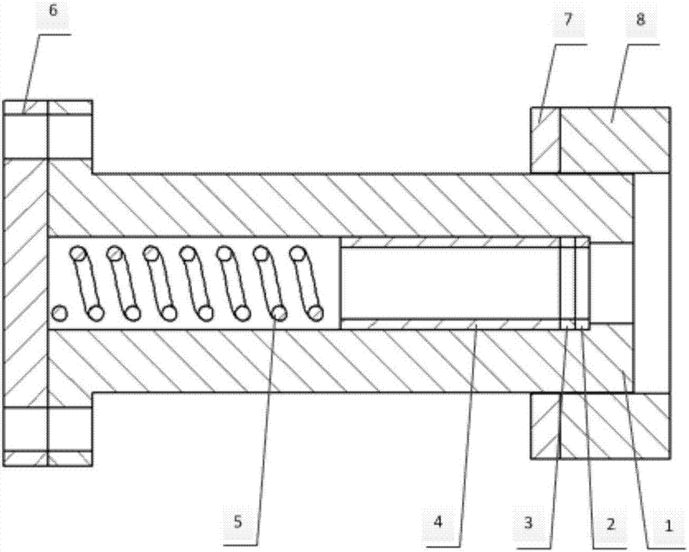
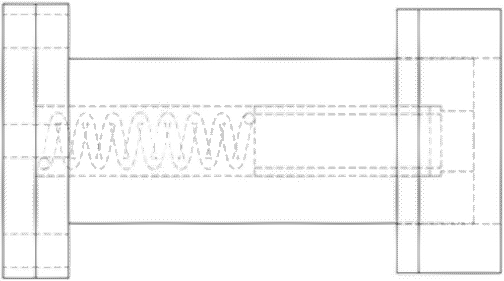
[0035] Such as figure 1 As shown, an annular micro-arc cathode discharge plasma propulsion device includes a sleeve 1, a first metal block 2, an insulating block 3, a second metal block 4, a spring 5, a flange 6, a magnetic core 7 and a permanent magnet 8 There is a stepped through hole in the sleeve 1, the first metal block 2, the insulating block 3, the second metal block 4 and the spring 5 are sequentially set in the stepped through hole and fit each other, the spring 5 and the flange 6 Fitting, the flange 6 is fixedly connected to one end of the sleeve 1 , the other end of the sleeve 1 is passed through the magnetic core 7 and the permanent magnet 8 , and the magnetic core 7 and the permanent magnet 8 are bonded.

[0036] The bonding surface of the first metal block 2 and the insulating block 3 is located in the same plane as the bon...


PUM

PropertyMeasurementUnit
thicknessaaaaaaaaaa

Abstract

The invention discloses an annular micro-arc cathode discharge plasma propulsion device, which comprises a sleeve, a first metal block, an insulating block, a second metal block, a spring, a magnetic core and a permanent magnet; the sleeve is provided with a stepped through hole, The first metal block, the insulating block, the second metal block and the spring are sequentially arranged in the stepped through hole and fit together, the spring is attached to the flange, the flange is fixedly connected to one end of the sleeve, and the other end of the sleeve is passed through the Among the magnetic core and the permanent magnet, the magnetic core is bonded to the permanent magnet. The present invention reduces the mass of the device by setting the sleeve, the first metal block, the insulating block and the second metal block, and solves the problem that the mass of the traditional miniature electric propulsion device is large; through the cooperation of the spring, the magnetic core and the permanent magnet, the extension The working time of the device is shortened, which makes up for the short working cycle of the traditional micro electric propulsion device; by controlling the relative positions of the first metal block and insulating block, the magnetic core and the permanent magnet, the accuracy of the device is improved, and the traditional micro electric propulsion device is overcome. Less precise puzzles.

Description

technical field [0001] The invention relates to an annular micro-arc cathode discharge plasma propulsion device, which is especially suitable for the space propulsion process of micro-nano satellites, and belongs to the technical field of micro-propulsion devices. Background technique [0002] With the development of modern science and technology, people gradually have new requirements for the cost of detection satellites and the production time period. Micro-nano-satellites are an important direction for the development of satellites in the future. Micro-nano-satellites have the advantages of low cost, small size, short development cycle, strong expansion capability, and flexible launch methods. When it is used, it is convenient for close-range, high-precision approaching monitoring and confrontation of the target, and at the same time, it will not be discovered by the target, which is of great significance in military operations. [0003] The long-term monitoring and high...

Claims


Application Information

Patent Timeline
Patent Type & Authority Applications(China)
IPC IPC(8): F03H1/00
CPCF03H1/0081
Inventor 耿金越龙军刘旭辉魏福智仝颖刚扈延林毛威陈君沈岩
Owner BEIJING INST OF CONTROL ENG
Why Eureka
Try Eureka