
Automatic demolding mold

A technology of automatic demoulding and moulding, applied in the direction of forming tools, manufacturing tools, metal processing equipment, etc., can solve the problems of wasting time, increasing defective products, easy to produce deviation in demoulding, and achieving a stable effect of demoulding

Inactive Publication Date: 2017-09-22
太仓市雅兴精密冲压件厂
View PDF9 Cites 0 Cited by
  • Summary
  • Abstract
  • Description
  • Claims
  • Application Information

AI Technical Summary

Problems solved by technology

[0003] The traditional mold is divided into an upper mold and a lower mold. The upper mold and the lower mold are set separately. When demoulding, the upper mold is pushed apart by the ejector pin and then demoulded. Since the ejector pin is used for demoulding, it is easy to produce deviations during demoulding. Greatly increases the probability of defective products, not only wasting materials, but also wasting time

Method used


Image

  • Automatic demolding mold

Examples


Embodiment Construction

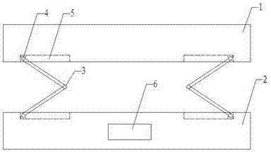
[0014] see figure 1 , the embodiment of the present invention includes: an automatic demoulding mold, including: an upper mold 1, a lower mold 2 and two electric folding rods 3, the upper mold 1 and the lower mold 2 are connected by two electric folding rods 3 The two ends of the electric folding rod 3 are respectively connected with the lower surface of the upper mold 1 and the upper surface of the lower mold 2, and the electric folding rod 3 is used for the upper mold 1 and the lower mold 2 separation.

[0015] The connection between the electric folding rod 3 and the lower surface of the upper mold 1 and the upper surface of the lower mold 2 is equipped with a rotating seat 4, and the rotating seat 4 is used for folding and opening the electric folding rod 3. turn.

[0016] Starting from the rotating seat 4, a rod groove 5 is opened toward the opposite direction of the two rotating seats 4 on the same horizontal plane, and the electric folding rod 3 is matched with the ro...


PUM


Abstract

The invention discloses an automatic demoulding mold, comprising: an upper mold, a lower mold and two electric folding rods, the upper mold and the lower mold are connected through the two electric folding rods; two ends of the electric folding rod They are respectively connected with the lower surface of the upper mold and the upper surface of the lower mold; the joints between the electric folding lever and the lower surface of the upper mold and the upper surface of the lower mold are equipped with a rotating seat, from the The rotating seat starts to open a rod groove toward the opposite direction of the two rotating seats on the same horizontal plane; a control panel is installed on the lower mold. Through the above method, the present invention provides an automatic demoulding mold. The mold is automatically demoulded through an electric folding rod without manpower, and the demoulding is more stable.

Description

technical field [0001] The invention relates to the field of molds, in particular to an automatic demoulding mold. Background technique [0002] Molds are various molds and tools used in industrial production for injection molding, blow molding, extrusion, die-casting or forging forming, smelting, stamping, stretching, etc. to obtain the required products. In short, molds are used to shape objects This tool is composed of various parts, and different molds are composed of different parts. It mainly realizes the processing of the shape of the article through the change of the physical state of the formed material. [0003] The traditional mold is divided into an upper mold and a lower mold. The upper mold and the lower mold are set separately. When demoulding, the upper mold is pushed apart by the ejector pin and then demoulded. Since the ejector pin is used for demoulding, it is easy to produce deviations during demoulding. The probability of defective products is greatly i...

Claims


Application Information

Patent Timeline
IPC IPC(8): B21D45/04B21D37/10
CPCB21D45/04B21D37/10
Inventor 浦雅斌
Owner 太仓市雅兴精密冲压件厂
Learn More