
Electric demolding mold

A demoulding and mold technology, applied in the field of electric demoulding molds, can solve the problems of increasing defective products, wasting time, wasting materials, etc., and achieve the effect of product integrity, stable demoulding, and labor reduction

Inactive Publication Date: 2017-09-22
SUZHOU TIANXINGSHAN PRECISION MOLD
View PDF5 Cites 0 Cited by
  • Summary
  • Abstract
  • Description
  • Claims
  • Application Information

AI Technical Summary

Problems solved by technology

[0002] The traditional mold is divided into an upper mold and a lower mold. The upper mold and the lower mold are set separately. When demoulding, the upper mold is pushed apart by the ejector pin and then demoulded. Since the ejector pin is used for demoulding, it is easy to produce deviations during demoulding. Greatly increases the probability of defective products, not only wasting materials, but also wasting time

Method used


Image

  • Electric demolding mold

Examples


Embodiment Construction

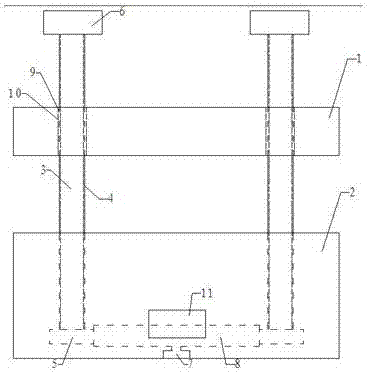
[0013] see figure 1 , the embodiment of the present invention includes: an electric demoulding mold, including: an upper mold 1, a lower mold 2 and two round rods 3, the upper mold 1 and the lower mold 2 are connected through the two round rods 3, The upper die 1 slides up and down on the round rod 3 .

[0014] The round rod 3 is fixed on the upper surface of the lower mold 2, and the two round rods 3 are symmetrically installed on the upper surface of the lower mold 2, so that the force is more balanced when demoulding.

[0015] The outer wall of the round rod 3 is provided with an external thread 4, the bottom end of the round rod 3 is equipped with a driven gear 5, and the top of the round rod 3 is equipped with a stopper 6, and the stopper 6 prevents the upper mold 1 from Demoulding is to slide out the round rod 3 .

[0016] The upper mold 1 is provided with a circular hole 9, and the circular hole 9 is provided with an internal thread 10, and the external thread 4 coope...


PUM


Abstract

The invention discloses an electric demolding mold comprising an upper mold, a lower mold and two round rods. The upper mold and the lower mold are connected through the two round rods. The round rods are fixed to the upper surface of the lower mold. The outer walls of the round rods are provided with outer threads. Driven gears are installed at the bottom ends of the round rods. Stop blocks are installed at the tops of the round rods. The upper mold is provided with round holes internally provided with inner threads. A motor is installed in the lower mold. A driving gear is installed on the motor and is connected with the driven gear. A control panel is installed on the surface of the lower mold. In this way, the electric demolding mold conducts demolding through rotation of the round rods, labor force is reduced, demolding is more stable, and a product is more complete.

Description

technical field [0001] The invention relates to the field of molds, in particular to an electric demoulding mold. Background technique [0002] The traditional mold is divided into an upper mold and a lower mold. The upper mold and the lower mold are set separately. When demoulding, the upper mold is pushed apart by the ejector pin and then demoulded. Since the ejector pin is used for demoulding, it is easy to produce deviations during demoulding. The probability of defective products is greatly increased, not only wasting materials, but also wasting time. Contents of the invention [0003] The technical problem mainly solved by the present invention is to provide an electric demoulding mold, which can be demolded by rotating a round rod. [0004] In order to solve the above technical problems, a technical solution adopted by the present invention is: an electric demoulding mold, comprising: an upper mold, a lower mold and two round rods, the upper mold and the lower mold...

Claims


Application Information

Patent Timeline
Patent Type & Authority Applications(China)
IPC IPC(8): B29C33/44
CPCB29C33/44
Inventor 贾宁霞
Owner SUZHOU TIANXINGSHAN PRECISION MOLD
Learn More