
punching device

A punching and stripping technology, applied in the field of continuous punching equipment, can solve the problems of difficult large-scale production requirements, low punching precision, and low processing efficiency, and achieve high processing efficiency, precise processing, and continuous punching Effect

Active Publication Date: 2019-01-04
GUANGDONG EVERWIN PRECISION TECH
View PDF5 Cites 0 Cited by
  • Summary
  • Abstract
  • Description
  • Claims
  • Application Information

AI Technical Summary

Problems solved by technology

[0002] Electronic devices often use connectors. During the processing of connectors, it is necessary to punch and bend the terminals of sheet metal sheets. However, the existing punching equipment has low processing efficiency and low punching accuracy. Low, difficult to meet large-scale production needs

Method used


Image

  • punching device
  • punching device
  • punching device

Examples


Embodiment Construction

[0027] In order to facilitate the understanding of the present invention, the present invention will be described more fully below with reference to the associated drawings. Preferred embodiments of the invention are shown in the accompanying drawings. However, the present invention can be embodied in many different forms and is not limited to the embodiments described herein. On the contrary, the purpose of providing these embodiments is to make the disclosure of the present invention more thorough and comprehensive.

[0028] It should be noted that when an element is considered to be "connected" to another element, it may be directly connected to the other element or there may be intervening elements at the same time. The terms "vertical," "horizontal," "left," "right," and similar expressions are used herein for purposes of illustration only and are not intended to represent the only embodiments.

[0029] Unless otherwise defined, all technical and scientific terms used h...


PUM


Abstract

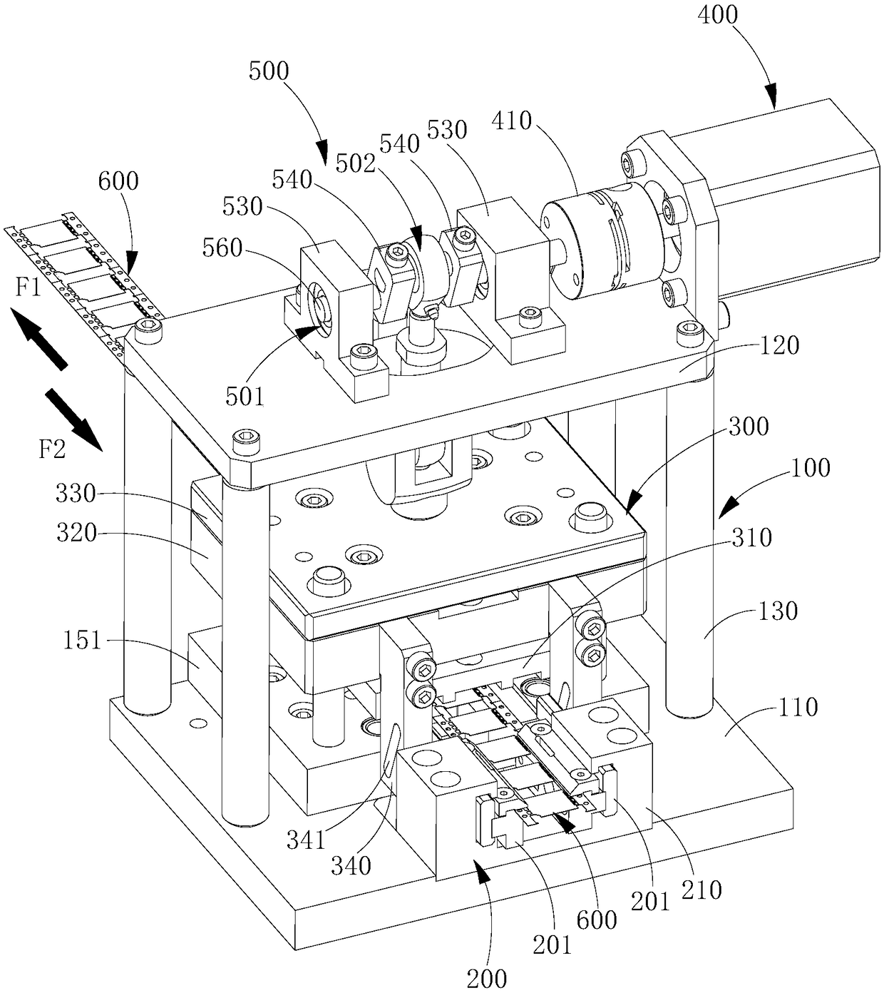
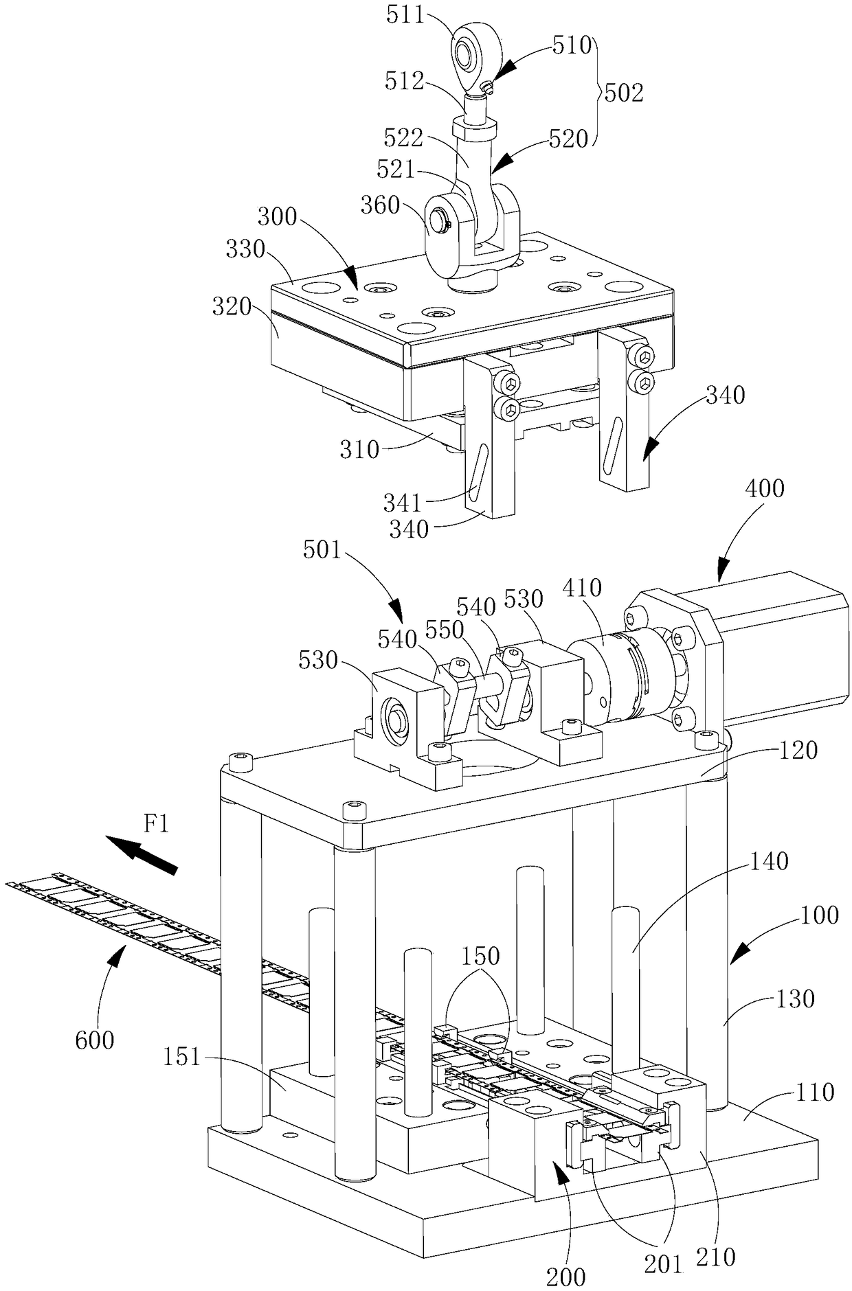
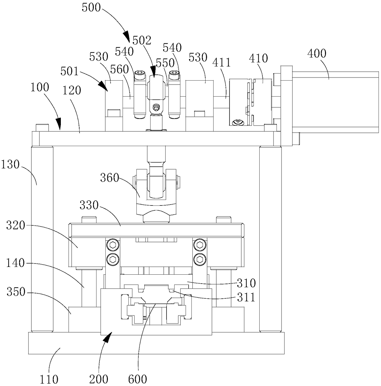
The invention relates a blanking device. The blanking device comprises a rack, a blanking mechanism, a feeding mechanism, a driving mechanism and a transmission mechanism, wherein the rack is provided with a support platform for supporting a material strap; the blanking mechanism is movably arranged on the rack, can ascend and descend relative to the rack and blanks and bends materials on the material strap on the support platform when descending; the feeding mechanism is arranged on the rack and linked with the blanking mechanism; and the driving mechanism is arranged on the tack, the transmission mechanism is connected between the driving mechanism and the blanking mechanism, the driving mechanism drives the blanking mechanism to ascend and descend through the transmission mechanism, and the feeding mechanism is driven to clamp and drive the material strap to move forwards when the blanking mechanism ascends, so that the blanking mechanism can continually blank and bend the materials on the material strap. According to the blanking device, the blanking mechanism and the feeding mechanism are linked and share the same power source, and the blanking device is accurate in processing and high in processing efficiency.

Description

technical field [0001] The invention relates to the field of continuous punching equipment, in particular to a punching device. Background technique [0002] Electronic devices often use connectors. During the processing of connectors, it is necessary to punch and bend the terminals of sheet metal sheets. However, the existing punching equipment has low processing efficiency and low punching accuracy. It is difficult to meet the needs of large-scale production. Contents of the invention [0003] Based on this, it is necessary to provide a punching device with high processing efficiency and high processing accuracy. [0004] A punching device, comprising: [0005] A frame, the frame is provided with a support platform for placing and supporting the strip; [0006] The punching mechanism is movably arranged on the frame and can be raised and lowered relative to the frame. When the punching mechanism descends, it punches and bends the material on the material belt on the s...

Claims


Application Information

Patent Timeline
Patent Type & Authority Patents(China)
IPC IPC(8): B21D28/02B21D28/20B21D43/00
CPCB21D28/02B21D28/20B21D43/00
Inventor 周伟
Owner GUANGDONG EVERWIN PRECISION TECH
Learn More