Clock generation circuitry

A technology of circuits and converter circuits, applied in the direction of generating electrical pulses, circuits, pulses, etc., can solve problems such as the difficulty of coupling oscillator phase offsets

Active Publication Date: 2017-09-19
SOCIONEXT INC
View PDF8 Cites 3 Cited by
  • Summary
  • Abstract
  • Description
  • Claims
  • Application Information

AI Technical Summary

Problems solved by technology

However, there are difficulties as to how to couple such an oscillator and how to control the phase offset
There is also a power penalty associated with providing such a circuit

Method used


Image

  • Clock generation circuitry
  • Clock generation circuitry
  • Clock generation circuitry

Examples


Embodiment Construction

[0040] The inventors have studied the corresponding figure 1 Circuits for Methods A, B, and C. However, they have identified the rather distant Rotating Traveling Wave Oscillator (RTWO) as suitable for quadrature signal generation taking into account the aforementioned ADC and DAC circuits.

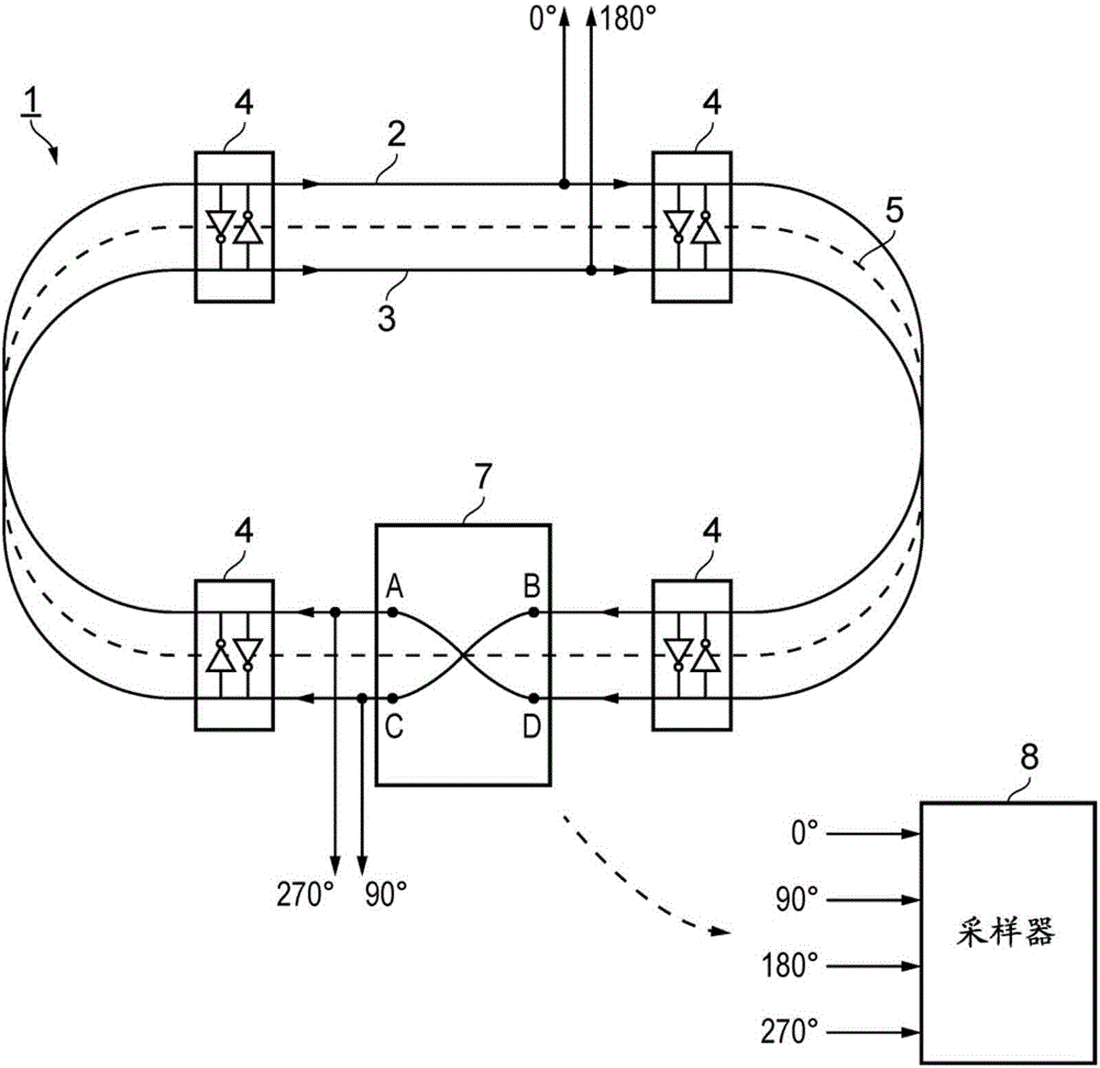
[0041] figure 2 is a schematic diagram of an example RTWO 1 for generating quadrature phase signals. The RTWO 1 includes a pair of signal lines 2 and 3 and a plurality of regeneration elements 4 .

[0042] Signal line 2 has ends A and B and signal line 3 has ends C and D. Signal lines 2 and 3 are connected end-to-end with end B connected to end C and end D connected to end A to form a closed or endless loop of signal lines. It should be understood that such signal lines may be realized as (ideal, lossless) transmission lines, and this disclosure will be read accordingly.

[0043] Note that the pair of signal lines 2 and 3 generally follow a path 5 which itself forms an endless loop....


PUM


Abstract

There is disclosed herein clock generation circuitry, in particular rotary travelling wave oscillator circuitry. Such circuitry comprises a pair of signal lines connected together to form a dosed loop and arranged such that they define at least one transition section where both said lines in a first portion of the pair cross from one lateral side of both said lines in a second portion of the pair to the other lateral side of both said lines in the second portion of the pair.

Description

technical field [0001] The present invention relates to clock generation circuits, in particular to clock generation circuits for generating and providing quadrature clock signals. Such quadrature clock signals may have relative phases of 0°, 90°, 180° and 270°, respectively. Background technique [0002] Quadrature clock signals may eg be required in DAC (Digital Analog Converter) circuits or ADC (Analog Digital Converter) circuits which may eg require four-phase interleaved substantially sinusoidal clock signals. Of course, such a clock generation circuit can also be used in applications other than DAC circuits and ADC circuits. [0003] An example of an ADC circuit required to generate quadrature clock signals can be found in EP 2211468, which is incorporated by reference into this application. An example of a DAC circuit which is also required to generate quadrature clock signals can be found in EP 2849345, which is likewise incorporated by reference into this applicat...

Claims


Application Information

Patent Timeline
Patent Type & Authority Applications(China)
IPC IPC(8): H03B5/18
CPCH03B5/1852H03B5/1805H03B5/1841H01L24/16H01L2224/16225H01L2924/14211H01L2924/14253H03B28/00H03M1/12H03M1/66H03B5/18H03K3/0315H03B2200/0016
Inventor 扬·朱索·德迪克大卫·蒂莫西·恩赖特
Owner SOCIONEXT INC
Why Eureka
Try Eureka