
A communication antenna and its installation and removal method

A communication antenna and mounting base technology, which is applied in the directions of antenna support/installation device, antenna coupling, and antenna grounding switch structure connection, etc. Responsiveness, Realization Utilization, Effect of Strong Concealment

Active Publication Date: 2019-09-13
36TH RES INST OF CETC
View PDF8 Cites 0 Cited by
  • Summary
  • Abstract
  • Description
  • Claims
  • Application Information

AI Technical Summary

Problems solved by technology

[0004] The invention provides a communication antenna and its installation and disassembly method to solve the problem that the performance of the antenna is greatly attenuated in the prior art, and the installation of the antenna inside the carrier platform will cause electromagnetic interference to other electronic equipment, affecting Other problems such as the normal operation of electronic equipment

Method used


Image

  • A communication antenna and its installation and removal method
  • A communication antenna and its installation and removal method
  • A communication antenna and its installation and removal method

Examples


Embodiment 1

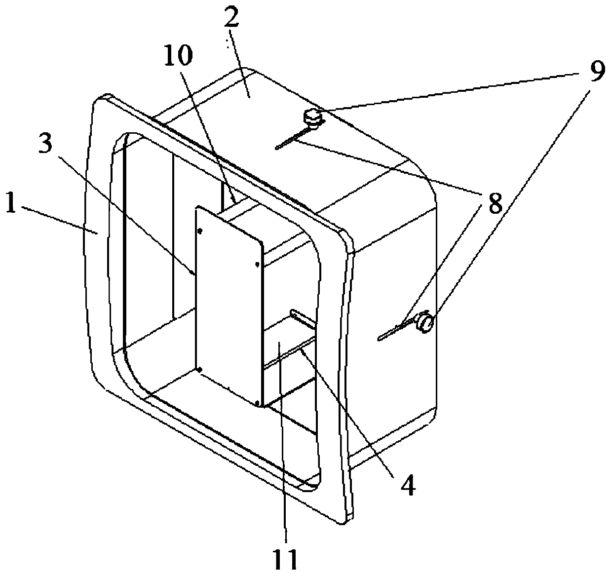
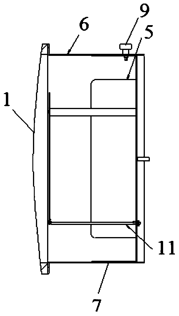
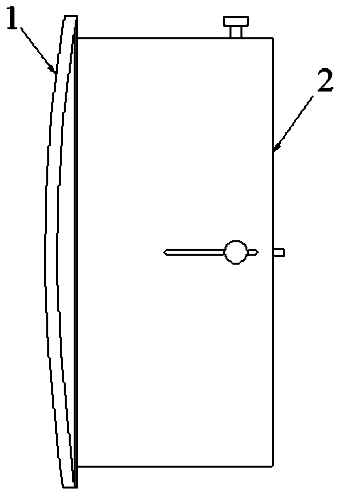
[0032] figure 1 is a schematic structural diagram of a communication antenna according to an embodiment of the present invention; figure 2 is a schematic side sectional view of a communication antenna according to an embodiment of the present invention; image 3 is an axial schematic diagram of a communication antenna according to an embodiment of the present invention.

[0033] see Figure 1 to Figure 3 , the communication antenna includes a mounting base 1, a back cavity 2, a microstrip antenna 3, and a radio frequency cable assembly 4; the mounting base 1 is used to paste and fix the position of the inner window of the carrier platform, and the back cavity 2 is fixed on the mounting base; the radio frequency cable One end of the core wire of the component 3 is installed on the conductive bottom plate 5 of the back cavity 2, the other end of the core wire is connected to the feeding point of the microstrip antenna 3, and the shielding layer of the radio frequency cable is...

Embodiment 2

[0036] This embodiment focuses on the description of the specific implementation of the communication antenna, and for other content, refer to other embodiments of the present invention.

[0037] The conductive bottom plate 5 is provided with a flanging structure 7 sleeved in the conductive enclosure 6, the flange structure 7 is provided with locking screw holes, and the position corresponding to the locking screw holes on the conductive enclosure 6 is provided with along The strip-shaped opening slot 8 in the height direction of the conductive enclosure 6 is provided with a locking screw 9 matched with the locking screw hole to extend into the opening slot 8 . In this way, the position of the conductive bottom plate 5 in the conductive enclosure 6 can be adjusted by loosening the locking screw 9 to adjust the distance between the microstrip antenna 3 and the carrying platform, and the conductive bottom plate 5 can be locked and fixed by the locking screw 9 Position within the...

Embodiment 3

[0040] This embodiment focuses on the description of the specific implementation of the communication antenna, and for other content, refer to other embodiments of the present invention.

[0041] The upper end of the microstrip antenna 3 is connected with the conductive bottom plate 5 of the back cavity 2 by two support rods 10, and the ground end of the lower end of the microstrip antenna 3 is connected with the conductive bottom plate 5 of the back cavity 2 by the support plate 11, and the support rods 10 The length is equal to the length of the support plate 11. In this way, the support rod 10 is used to install the upper end of the microstrip antenna 3 on the conductive bottom plate 5 of the back chamber 2; The ground terminal of the antenna 3 is connected to the conductive bottom plate 5 . The length of the radio frequency cable assembly 4 is determined by the length of the support bar 10, the radio frequency cable assembly 4 includes a section of radio frequency cable a...


PUM


Abstract

The invention discloses a communication antenna and a mounting and detaching method therefor. The communication antenna comprises a mounting base, a back cavity, a microstrip antenna and a radio frequency cable assembly; the mounting base is used for being pasted and fixed in the position of an internal window of a carrying platform, and the back cavity is fixed in the mounting base; one end of a core wire of the radio frequency cable assembly is mounted on a conductive bottom plate of the back cavity while the other end of the core wire is connected with a feed point of the microstrip antenna; a radio frequency cable shielding layer is grounded; a microstrip antenna is fixedly connected with the conductive bottom plate of the back cavity; and the height between the conductive bottom plate and the mounting base is adjustable. The communication antenna provided by the invention is free of transformation on the mounting platform, capable of being mounted and detached rapidly and high in imperceptibility; the communication antenna can be rapidly mounted in a traceless manner when a temporary task is executed; the original shape can be recovered rapidly in retraction, so that high imperceptibility is realized; and meanwhile, electromagnetic interference to other electronic equipment in the platform can be avoided in operation, and electromagnetic compatibility to the equipment is also achieved.

Description

technical field [0001] The invention relates to the technical field of communication equipment, in particular to a communication antenna and its installation and removal method. Background technique [0002] At present, many delivery platforms have their own communication equipment, but the signal channels of these communication equipment are public and can be easily cracked and monitored. Therefore, it is sometimes necessary to install communication equipment in other frequency bands. In order to make the communication more concealed and confidential, it is sometimes necessary to conceal the additional antenna, which cannot be easily distinguished from the appearance. [0003] There are three ways to install concealed antennas: one is to transform the existing antenna equipment to increase its compatibility; the other is to specially design the antenna conformal to the shape; the third is to transfer the antenna to the inside of the platform. The first method needs to rede...

Claims


Application Information

Patent Timeline
Patent Type & Authority Patents(China)
IPC IPC(8): H01Q1/12H01Q1/27H01Q1/50H01Q1/52
Inventor 钱志伟王一
Owner 36TH RES INST OF CETC
Learn More