
Touch panel

A touch panel and touch circuit technology, which is applied in the fields of instrumentation, computing, electrical and digital data processing, etc., can solve problems such as abnormal circuit function, poor gate output, and subsequent gates cannot be output smoothly and sequentially.

Active Publication Date: 2017-09-15
AU OPTRONICS CORP
View PDF5 Cites 3 Cited by
  • Summary
  • Abstract
  • Description
  • Claims
  • Application Information

AI Technical Summary

Problems solved by technology

When the sensing is completed and the signal starts to output, the circuit of this stage will produce a poor gate output because the potential of the Q point is too low
If the situation is serious, it will cause no output of the gate of this stage, resulting in abnormal circuit function
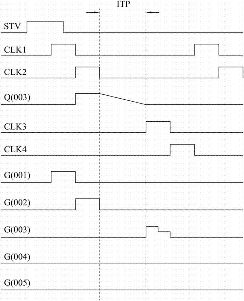
by Figure 1A and Figure 1B For example, after the output of G(002) is completed, the Q point (Q003) of the stage of G(003) has been pre-charged to a high potential, and the embedded touch sensor starts to sense at this time. In the input signal (ITP) detection interval, all GOA signals are non-output. Since the ITP detection interval is as long as 200 microseconds, the potential of Q(003) will drop from high potential all the way due to the leakage of the pull-down circuit of this stage.
When the sensing is completed and the timing signal CLK3 is input, G(003) starts to output, but because the potential of Q(003) is insufficient, the pulse wave of G(003) will become worse or there will be no output. In this way, it will cause Subsequent gates cannot be output smoothly and sequentially

Method used


Image

  • Touch panel
  • Touch panel
  • Touch panel

Examples


Embodiment Construction

[0065] A number of embodiments of the present invention will be disclosed in the following figures. For the sake of clarity, many practical details will be described together in the following description. It should be understood, however, that these practical details should not be used to limit the invention. That is, in some embodiments of the present invention, these practical details are unnecessary. In addition, for the sake of simplifying the drawings, some well-known structures and components will be shown in a simple and schematic manner in the drawings.

[0066] As used herein, "comprising", "comprising", "having", "comprising" and so on are all open terms, meaning including but not limited to.

[0067]As used herein, "and / or" includes any or all combinations of the stated things. In addition, regarding the "connection", "electrical connection", and "electrical coupling" used in this article, if it is stated that it must be direct, the connection relationship between...


PUM


Abstract

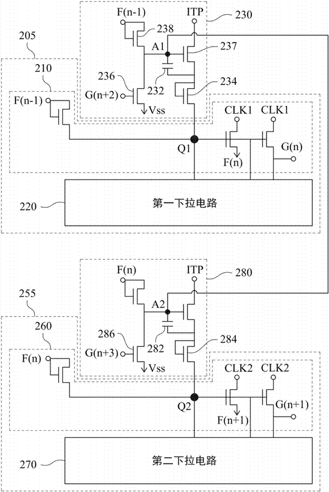
The present invention discloses a touch panel comprising a first gate drive circuit, a first touch circuit, a second gate drive circuit and a second touch circuit. Wherein the first touch circuit is connected to the first gate drive circuit and the first touch circuit has a first capacitance. The second touch circuit is connected to the second gate drive circuit and the second touch circuit has a second capacitor, wherein the first capacitor is connected in parallel with the second capacitor.

Description

technical field [0001] The invention relates to a touch panel. Background technique [0002] Figure 1A A structural diagram showing a prior art touch panel, Figure 1B draw Figure 1A The waveform diagram of the signal output by the circuit. As far as the existing technology of in-cell touch is concerned, when in-cell touch sensing is being performed, in order to avoid sensing errors caused by other noise interference, it is required that a Gate driver on array circuit (Gate driver on array circuit, The output of the GOA) signal is suspended, that is, the timing signals CLK1 - CLK4 and the trigger signal STV are all at low potential during the sensing period. After the sensing is over, the signal after the previous pause continues to be output. In this case, if no changes are made, the pull-down circuit inside the GOA will generate a leakage current when the in-cell touch sensing is performed, so that the Q point potential of the current level GOA will be affected by the...

Claims


Application Information

Patent Timeline
IPC IPC(8): G06F3/044
CPCG06F3/044G06F3/0412G09G3/20G09G2310/0267G09G2310/0286G06F3/04184
Inventor 陈柄霖
Owner AU OPTRONICS CORP
Learn More