
Shared recording control system and realization method

A technology of control system and implementation method, applied in static memory, instrument, signal processing, etc., which can solve problems such as equipment overlap, difficulty in recording room collaboration, and inability to edit synchronously

Active Publication Date: 2018-02-23
郭思明
View PDF13 Cites 2 Cited by
  • Summary
  • Abstract
  • Description
  • Claims
  • Application Information

AI Technical Summary

Problems solved by technology

[0002] At present, in the field of audio recording technology, the electronic tube headphone amplifier distributor and the electronic tube microphone amplifier adopt analog transmission mode. The signal also directly enters the mixer or recording sound card, and then enters the computer for editing from the mixer or recording sound card, which leads to the fact that each recording room must have an independent system, including computers, mixers or sound cards, microphone amplifiers, Headphone amplifier distributor, etc.; this will cause overlapping of equipment, waste of resources, equipment cannot be shared, collaboration between recording rooms is difficult, and online synchronization cannot be edited in time, etc.

Method used


Image

  • Shared recording control system and realization method
  • Shared recording control system and realization method
  • Shared recording control system and realization method

Examples


Embodiment Construction

[0050] In order to make the object, technical solution and advantages of the present invention more clear and definite, the present invention will be further described in detail below with reference to the accompanying drawings and examples. It should be understood that the specific embodiments described here are only used to explain the present invention, not to limit the present invention.

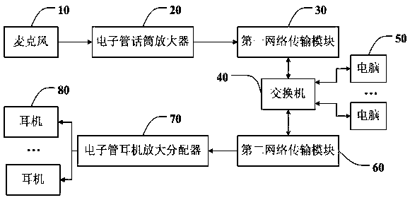
[0051] See figure 1 , figure 1 It is a functional principle block diagram of a preferred embodiment of the shared recording control system of the present invention. Such as figure 1 As shown, a shared recording control system, wherein the shared recording control system includes:

[0052]Microphone 10, electronic tube microphone amplifier 20, first network transmission module 30, switch 40, computer 50, second network transmission module 60, electronic tube earphone amplifier distributor 70, earphone 80; specifically, described electronic tube microphone amplifier 20 and described Th...


PUM


Abstract

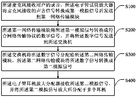
The invention discloses a shared recording control system and a realization method. The system comprises an electron tube microphone amplifier which is used for converting sound signals into first analog signals and then sending the first analog signals to a first network transmission module, wherein the first network transmission module is used for converting the first analog signals into digitalsignals; a switch which is connected with the first network transmission module and a plurality of computers and is used for receiving the digital signals and sending the digital signals to a secondnetwork transmission module, wherein the plurality of computers which are used for carrying out online synchronous monitoring and edition; the second network transmission module which is connected with the switch and is used for receiving the digital signals and converting the digital signals into second analog signals; and an electron tube earphone amplifier distributor which is connected with the second network transmission module and is used for receiving the second analog signals, amplifying the second analog signals and allocating the amplified signals to a plurality of earphones. According to the system and the method, multiway audio signals are transmitted through a network cable; the computers in a local area network can carry out online synchronous monitoring and edition; the working efficiency is greatly improved; resources are saved to the greatest extent; and the cost is reduced.

Description

technical field [0001] The invention relates to the technical field of audio recording, in particular to a shared recording control system and an implementation method. Background technique [0002] At present, in the field of audio recording technology, the electronic tube headphone amplifier distributor and the electronic tube microphone amplifier adopt analog transmission mode. The signal also directly enters the mixer or recording sound card, and then enters the computer for editing from the mixer or recording sound card, which leads to the fact that each recording room must have an independent system, including computers, mixers or sound cards, microphone amplifiers, Headphone amplifier distributor, etc.; this will cause overlapping of equipment, waste of resources, equipment cannot be shared, collaboration between recording rooms is difficult, and online synchronization cannot be edited in time and other defects. [0003] Therefore, the prior art still needs to be imp...

Claims


Application Information

Patent Timeline
IPC IPC(8): H04R3/12G11C7/16
CPCG11C7/16H04R3/12H04R2430/00
Inventor 郭思明
Owner 郭思明
Learn More