Pull-out cooling kit

A kit and pull rod technology, applied in the field of lighting, can solve the problems of large local stress in the packaging structure, more cost, and depression in the corresponding area of ​​the packaging structure.

Active Publication Date: 2019-08-06
东莞市闻誉实业有限公司
View PDF2 Cites 0 Cited by
  • Summary
  • Abstract
  • Description
  • Claims
  • Application Information

AI Technical Summary

Problems solved by technology

[0003] However, in actual situations, in order to improve the heat dissipation performance of the heat dissipation component, especially in order to increase the heat dissipation surface area of ​​the heat dissipation component, usually, the heat dissipation component will be provided with sheet-shaped, prismatic, column-shaped or / and dot-shaped and other structures used to increase the heat dissipation surface area, although these structures can better improve the heat dissipation surface area of ​​the heat dissipation components, but due to these protruding structures, there are more discontinuous surfaces, that is, the overall surface is not smooth enough, and the , these protruding structures will generate large local stress on the packaging structure, which is easy to cause its own bending, and also easy to cause problems such as depressions in the corresponding areas of the packaging structure, and because the surface is not smooth enough, it will cost more packaging Material, that is to say, the existing heat dissipation components are not flat enough in the overall structure during packaging and transportation, which increases the restrictions on packaging operations, that is, the number of heat dissipation components that can be accommodated in the unit packaging space is small

Method used


Image

  • Pull-out cooling kit
  • Pull-out cooling kit
  • Pull-out cooling kit

Examples


Embodiment Construction

[0024] In order to facilitate the understanding of the present invention, the present invention will be described more fully below with reference to the associated drawings. Preferred embodiments of the invention are shown in the accompanying drawings. However, the present invention can be embodied in many different forms and is not limited to the embodiments described herein. On the contrary, the purpose of providing these embodiments is to make the disclosure of the present invention more thorough and comprehensive.

[0025] It should be noted that when an element is referred to as being “fixed” to another element, it can be directly on the other element or there can also be an intervening element. When an element is referred to as being "connected to" another element, it can be directly connected to the other element or intervening elements may also be present. The terms "vertical," "horizontal," "left," "right," and similar expressions are used herein for purposes of ill...


PUM


Abstract

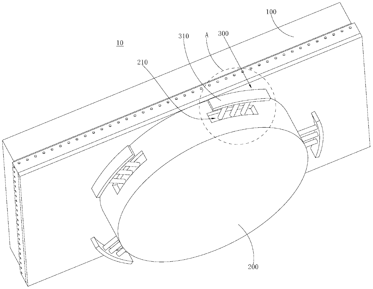
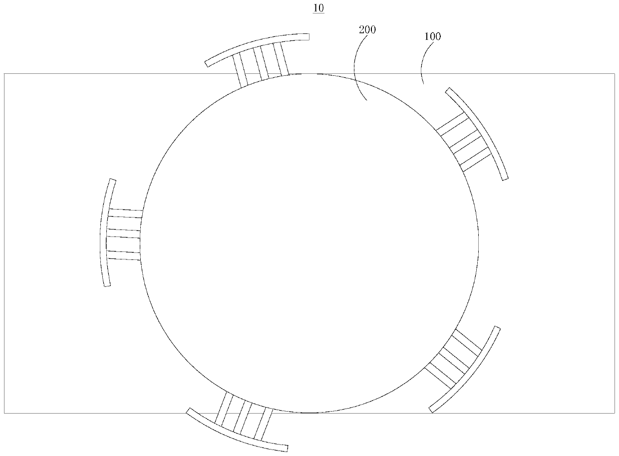
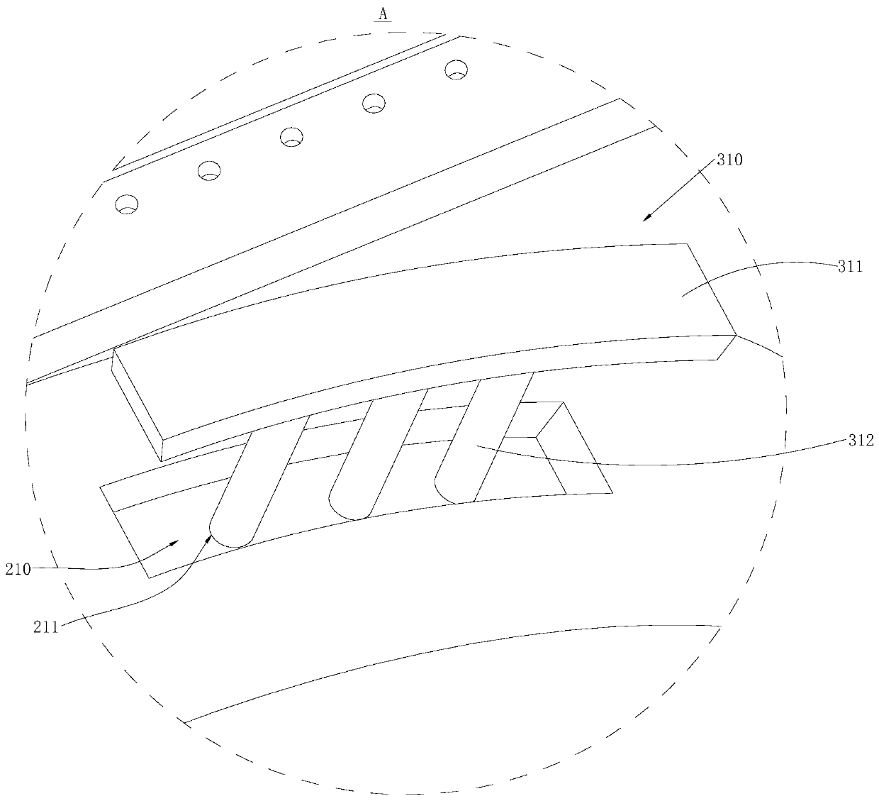
A drawing and pulling type cooling complete part comprises a heat amount treatment base, a mounting base table and a drawing and pulling assembly; the mounting base table is arranged on the heat amount treatment base, and is of a cylindrical structure, multiple mounting grooves are formed in the mounting base table in the radial direction, and multiple drawing and pulling holes are formed in the bottom of each mounting groove; the drawing and pulling assembly comprises multiple drawing and pulling parts, each drawing and pulling part is correspondingly mounted on a mounting groove, and each drawing and pulling part comprises a cooling arc piece and multiple cooling drawing and pulling rods; the first ends of the drawing and pulling rods penetrate in the drawing and pulling holes in a one-to-one correspondence sliding manner, and the second ends of the drawing and pulling rods are connected with the cooling arc pieces; in the transport process, the cooling arc pieces and the drawing and pulling rods are contained in the mounting grooves and the drawing and pulling holes correspondingly, in the unit package space, more drawing and pulling type cooling complete parts can be contained, when the complete part needs to be used, the cooling arc pieces and the drawing and pulling rods are pulled out, the cooling area of the whole structure can be improved, and the cooling property is better.

Description

technical field [0001] The invention relates to the technical field of lighting, in particular to a pull-out cooling kit. Background technique [0002] At present, a lamp refers to an appliance that can transmit light, distribute and change the light distribution of the light source, including all parts required to fix and protect the light source except the light source, as well as the necessary line accessories for connection to the power supply, and also need to install heat dissipation components to ensure proper cooling performance. [0003] However, in actual situations, in order to improve the heat dissipation performance of the heat dissipation component, especially in order to increase the heat dissipation surface area of ​​the heat dissipation component, usually, the heat dissipation component will be provided with sheet-shaped, prismatic, column-shaped or / and dot-shaped and other structures used to increase the heat dissipation surface area, although these struct...

Claims


Application Information

Patent Timeline
Patent Type & Authority Patents(China)
IPC IPC(8): F21S8/00F21V17/10F21V19/00F21V29/77F21V29/70F21Y115/10
CPCF21S8/00F21V17/10F21V19/001F21V29/70F21V29/77F21Y2115/10
Inventor 叶伟炳
Owner 东莞市闻誉实业有限公司
Why Eureka
Try Eureka