High-frequency chain matrix type inverter topology with front stage being dual Buck-Boost inverters and modulation method thereof

A matrix converter and inverter technology, which is applied in the output power conversion device, the conversion of AC power input to DC power output, electrical components, etc. problem, to achieve the effect of wide application scalability, easy implementation, and flexible control

Inactive Publication Date: 2017-09-08
YANSHAN UNIV
View PDF1 Cites 5 Cited by
  • Summary
  • Abstract
  • Description
  • Claims
  • Application Information

AI Technical Summary

Problems solved by technology

In the application, the method of changing the turn ratio of the power frequency transformer at its output end is often used to achieve further boosting, but at the same time, the volume and weight of the power device are increased, which affects the popularization and use of this type of converter.

Method used


Image

  • High-frequency chain matrix type inverter topology with front stage being dual Buck-Boost inverters and modulation method thereof
  • High-frequency chain matrix type inverter topology with front stage being dual Buck-Boost inverters and modulation method thereof
  • High-frequency chain matrix type inverter topology with front stage being dual Buck-Boost inverters and modulation method thereof

Examples


Embodiment Construction

[0027]The present invention will be further described below in conjunction with accompanying drawing:

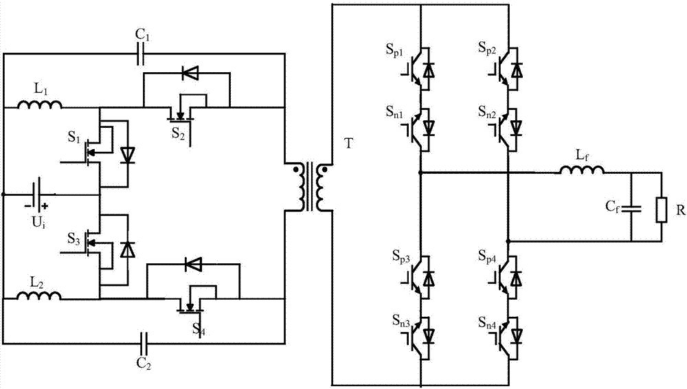
[0028] The topology of the high-frequency chain matrix inverter with double Buck-Boost front stage in the present invention is composed of double Buck-Boost inverters, high-frequency transformer T, matrix converter, and LC type filter connected in sequence; The inverter circuit is a double Buck-Boost circuit, and the output of the two sets of Buck-Boost is differenced to obtain a positive and negative alternating high-frequency square wave, which is coupled to the secondary side of the transformer by a high-frequency transformer and modulated by a matrix converter in the rear stage of the transformer. , output power frequency sinusoidal voltage by filter.

[0029] The front stage is a dual Buck-Boost inverter circuit with a DC input voltage U i , power switch tube S 1 , power switch tube S 2 , power switch tube S 3 , power switch tube S 4 , inductance L 1 , inductance ...


PUM


Abstract

The invention relates to a high-frequency chain matrix type inverter topology with a front stage being dual Buck-Boost inverters and a modulation method thereof. A front-stage inverter topology is formed by sequentially connecting the dual Buck-Boost inverters, a high-frequency transformer T, a matrix converter and an LC filter. According to a front stage modulation method, a pulse width modulation (PWM) wave generated by a PWM signal generation link is processed, the buck-boost function is achieved by changing a duty ratio, so that the difference between working mode states of the two groups of Buck-Boost converters is 180 degrees, namely, one group works in a boost state, the other group works in a buck state, and positive square waves and negative square waves which are alternative can be obtained by subtracting the square waves output by the two groups, and the function of inversion is achieved; and according to a rear stage modulation method, logic processing is performed on the PWM wave generated by the PWM signal generation link and a sinusoidal pulse width modulation (SPWM) wave generated by an SPWM signal generation link, a high-frequency square wave output from the transformer is converted to a power frequency sine wave, and the front stage and the rear stage employ synchronous PWM signals to perform coordinated modulation. The high-frequency chain matrix type inverter topology has the advantages of simple modulation mode, relatively flexibility in control, wide application expandability and the like, and bidirectional energy flowing can be achieved.

Description

technical field [0001] The invention relates to the field of power electronic power converter topology and modulation, in particular to a circuit topology and modulation method using a double Buck-Boost circuit as the front stage of a high-frequency chain matrix inverter. Background technique [0002] An inverter is a topological device that converts DC power into AC power. The biggest difference between high-frequency chain inverter technology and conventional inverter technology is that it uses high-frequency transformers to realize energy transfer and electrical isolation between input and output, thereby reducing the volume and weight of transformers, reducing costs, improving power utilization, and improving energy efficiency. the working characteristics of the inverter. [0003] According to the circuit topology, the high frequency link inverter can usually be divided into DC / DC conversion type (DC-HFAC-DC-LFAC) and matrix conversion type (DC-HFAC-LFAC), among them, H...

Claims


Application Information

Patent Timeline
Patent Type & Authority Applications(China)
IPC IPC(8): H02M7/5387H02M7/5395
CPCH02M7/5387H02M7/5395
Inventor 闫朝阳梁晨阳孙喆李建霞李春蕾
Owner YANSHAN UNIV
Why Eureka
Try Eureka