
Locomotive traction inverter

A traction inverter and locomotive technology, which is applied in the conversion of equipment structural parts, AC power input into DC power output, cooling/ventilation/heating transformation, etc., can solve the difficulty of high power density, locomotive traction inverter structure Not the same and other problems, to achieve the effect of satisfying the space

Active Publication Date: 2017-09-08
CRRC YONGJI ELECTRIC CO LTD
View PDF10 Cites 2 Cited by
  • Summary
  • Abstract
  • Description
  • Claims
  • Application Information

AI Technical Summary

Problems solved by technology

Therefore, it is very difficult for the locomotive traction inverter device to increase the high power density in a narrow space and meet the electrical performance requirements.
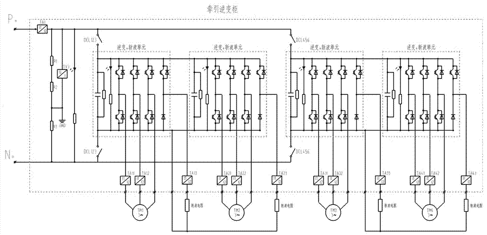
[0003] At present, the structures of traction inverters for locomotives are different, and most of them are water-cooled cooling structures, while air-cooled inverters for internal combustion locomotives have not yet been reported and implemented.

Method used


Image

  • Locomotive traction inverter
  • Locomotive traction inverter
  • Locomotive traction inverter

Examples


Embodiment Construction

[0013] Specific embodiments of the present invention will be described in detail below in conjunction with the accompanying drawings.

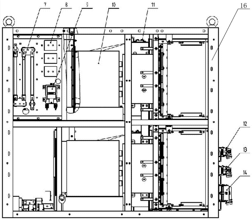
[0014] It can be seen from Figure 2 that the traction inverter has other auxiliary circuits besides four 500KW inverter choppers. From the perspective of the main technical requirements of the traction inverter, it is very difficult to arrange four inverter choppers in such a small space, and it also needs to adopt an air-cooled structure.

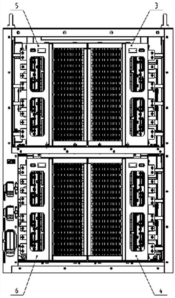
[0015] In order to optimize the design, the traction inverter adopts a modular design, including 4 power inverter output and chopper braking units, 1 traction motor and power frequency power supply conversion switch, 1 grounding detection unit, and 5 high-voltage indicating devices , and forced air cooling unit, safety discharge protection and related detection unit.

[0016] Specifically, the layout scheme is that the locomotive traction inverter includes a cabinet body 16, and the cabinet body 16 is div...


PUM


Abstract

The invention discloses a locomotive traction inverter, which comprises a cabinet body, and is characterized in that the cabinet body is divided into two layers, a power module 1 and a power module 3 are parallelly installed at the right side of the cabinet body at the upper layer, two support capacitor are parallelly installed at the left side of the cabinet body at the power layer, in the same way, a power module 2 and a power module 4 are parallelly installed at the right side of the cabinet body at the lower layer, and two support capacitors are parallelly installed at the left side of the cabinet body at the lower layer; a cooling fan is respectively installed between the support capacitors located in the cabinet body at the upper and lower layers; an installation plate is arranged at the front side of the cooling fan located at the upper layer, a change-over switch is arranged at the rear side of the cooling fan located at the upper layer, the installation plate is provided with a grounding resistor, a voltage detecting plate and a voltage sensor; discharge resistors are arranged at the cabinet body front and rear side surfaces of the power modules; and a secondary terminal X4, a secondary terminal X2 and a secondary terminal X1 are arranged at right lower part of the cabinet body. The locomotive traction inverter disclosed by the invention is different from previous locomotive traction inverters in design structure, and requirements in space, electrical performance and mechanical performance of the inverter are met at the same time.

Description

technical field [0001] The invention relates to railway locomotive equipment, in particular to an arrangement structure of a railway locomotive traction inverter. Background technique [0002] Railway locomotives are important equipment related to personnel safety, especially in the era when Chinese railways are connected to the world and locomotives are going global, the locomotives are required to have very high reliability. Therefore, it is very difficult for the locomotive traction inverter device to increase the high power density in a narrow space and meet the electrical performance requirements. [0003] At present, the structures of traction inverters for locomotives are different, and most of them are water-cooled cooling structures, while air-cooled inverters for internal combustion locomotives have not been reported and implemented yet. Contents of the invention [0004] The object of the invention is to provide a locomotive traction inverter by designing and l...

Claims


Application Information

Patent Timeline
Patent Type & Authority Applications(China)
IPC IPC(8): H02M7/00H05K7/20
CPCH02M7/003H05K7/20909
Inventor 李竹可黄超王龙刚唐丽欢张西哲李兵侯涛
Owner CRRC YONGJI ELECTRIC CO LTD
Learn More