
Wearable optical fiber probe

A fiber optic probe, wearable technology, applied in the direction of Raman scattering, material excitation analysis, etc., to achieve the effect of easy fixing and testing, wide range of use, and good man-machine combination effect

Inactive Publication Date: 2017-09-08
浙江澍源智能技术有限公司
View PDF5 Cites 1 Cited by
  • Summary
  • Abstract
  • Description
  • Claims
  • Application Information

AI Technical Summary

Problems solved by technology

[0009] The purpose of the present invention is to provide a method that can detect the spectrum stably and accurately in view of the shortcomings of the current traditional optical probe in human body detection, and the advantages of optical detection technologies such as Raman spectrum, infrared spectrum, and fluorescence spectrum in the non-invasive detection of the human body. Comfortable and safe fiber optic probes for body wear

Method used


Image

  • Wearable optical fiber probe
  • Wearable optical fiber probe
  • Wearable optical fiber probe

Examples


Embodiment 1

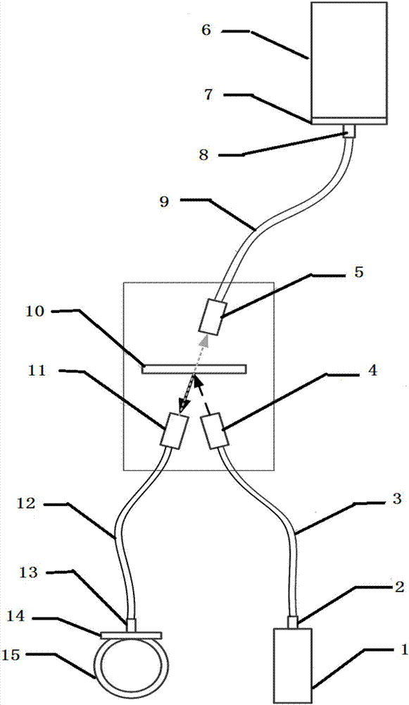
[0036] This embodiment provides a wearable optical fiber probe, such as figure 1 As shown, it includes a laser channel, a Raman scattering collection channel, and a detection channel, and the laser channel is connected to the detection channel through a filter;

[0037] The incident optical fiber 3, the first collimating lens 4, and the first optical filter 10 are sequentially arranged in the laser channel along the propagating direction of the incident laser light;

[0038] The incident optical fiber 3 transmits the incident laser light to the first collimating lens 4, and the direction of the incident laser light is controlled by the first collimating lens 4, so that the incident laser light is accurately directed to the first optical filter 10, and the first optical filter 10 Only lasers with specific wavelengths are allowed to pass through;

[0039] The detection channel is respectively connected to the laser channel and the Raman scattering channel through the first opti...

Embodiment 2

[0050] On the basis of Embodiment 1, this embodiment further includes a wristband 15 on which the self-focusing lens 13 is arranged.

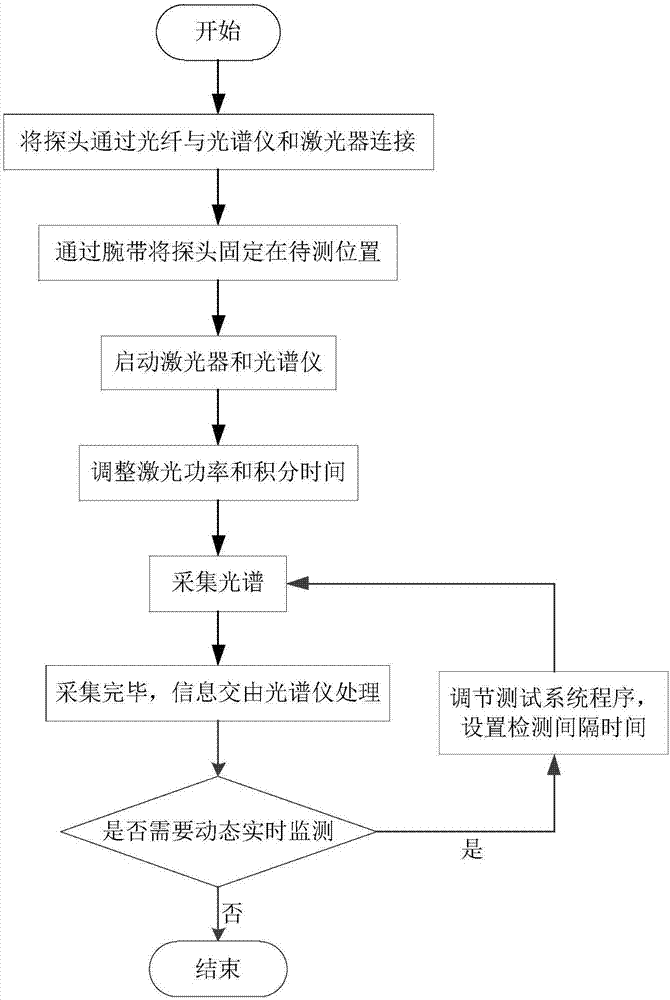
[0051] The probe provided in Embodiment 1 can be fixed on a living body, especially a human body (such as a human wrist, arm, etc.) through a wrist strap and Velcro, not only capable of single detection, but also dynamic real-time monitoring.

Embodiment 3

[0053] In this embodiment, on the basis of Embodiment 2, a light blocking plate 14 is provided between the self-focusing lens 13 and the wristband 15 to prevent the laser from directly striking the human body.


PUM

PropertyMeasurementUnit
wavelengthaaaaaaaaaa
reflectanceaaaaaaaaaa

Abstract

The invention discloses a wearable optical fiber probe. The wearable optical fiber probe comprises a housing, the housing is internally provided with a laser channel and a Raman scattering collection channel, the laser channel and the Raman scattering collection channel are mutually parallel, the wearable optical fiber probe further comprises a detection channel, the laser channel is connected with the detection channel through an optical filter; an incident optical fiber, a first collimating lens and the optical filter are sequentially arranged in the laser channel in the spreading direction of the incident laser; a second collimating lens, a detection optical fiber and a self-focusing lens are sequentially arranged in the detection channel in the spreading direction of the reflection laser obtained after the incident laser is reflected by the optical filter; the optical filter, a third collimating lens and a collection optical fiber are sequentially arranged in the Raman scattering collection channel along the Raman reflection direction of the reflection laser. The self-focusing lens is used as the collection lens, a light source is guaranteed to be converged to the surface of a detected object, the fact that no gap exists between the probe and the detected object is guaranteed, a signal in the environment is prevented from entering the probe; moreover, the focusing position is not affected by the degree of tightness and the motion of a wrist strap and the like, so that the spectral information is guaranteed to be accurately collected.

Description

technical field [0001] The invention relates to the field of optical detection and material analysis, in particular to the field of real-time accurate and non-invasive detection and qualitative and quantitative analysis of substances at the same point of the sample to be measured by using the spectral analysis method on the micrometer scale. Background technique [0002] In recent years, optical detection technology, especially wearable non-invasive detection equipment suitable for the human body, has become more and more popular. Optical detection technologies such as Raman spectroscopy, infrared spectroscopy, and fluorescence spectroscopy have been applied to the detection of human physiological indicators. [0003] Raman spectroscopy (Raman) can reveal the vibrational modes of molecules and crystals of organic and inorganic substances, and Raman spectrometers can identify material components through the frequency shift information of Raman spectroscopy. Applying it to th...

Claims


Application Information

Patent Timeline
Patent Type & Authority Applications(China)
IPC IPC(8): G01N21/65
CPCG01N21/65
Inventor 彭波郑毅高飞朱香平聂荣志
Owner 浙江澍源智能技术有限公司
Learn More