Spherical parallel mechanism

A technology of parallel connection and machine base, which is applied in the direction of manipulators, program-controlled manipulators, manufacturing tools, etc. It can solve the problems of changing the load transfer characteristics of parallel mechanisms, reducing the load transfer efficiency of moving platforms, and affecting the working performance of moving platforms, so as to improve the load capacity. and motion accuracy, improve work performance, and increase stiffness

Active Publication Date: 2017-09-08
DONG GUAN AICREATE ROBOT TECH CO LTD +1
View PDF9 Cites 4 Cited by
  • Summary
  • Abstract
  • Description
  • Claims
  • Application Information

AI Technical Summary

Problems solved by technology

[0004] However, due to the limitation of the singular configuration, the rotation capacity of the actuation platform of the parallel mechanism is often relatively small. Even a relatively simple planar parallel mechanism can theoretically achieve The rotation range of the moving platform does not exceed 180°, which is actually smaller; the singular configuration also affects the flexibility of the moving platform, because the load transfer efficiency of the moving platform drops sharply when it is close to the singular configuration; in addition, the kinematic branch chain of the mechanism When it is less, the carrying capacity is also poor, which affects the working performance of the moving platform
[0005]Redundant drive parallel mechanism is a parallel mechanism with more input members than output degrees of freedom. Some parallel mechanisms will assist the platform to cross the singularity by adding redundant drive branches configuration, so as to obtain greater rotation capacity, but the redundant drive will lead to over-constraint and generate internal force, which makes the mechanism face complex control problems; some parallel mechanisms choose to add redundant drives in some branch chains, but This leads to the emergence of hybrid structures, which change the load transfer characteristics of the original parallel mechanism

Method used


Image

  • Spherical parallel mechanism
  • Spherical parallel mechanism
  • Spherical parallel mechanism

Examples


Embodiment Construction

[0035] In order to facilitate the understanding of those skilled in the art, the present invention will be further described below in conjunction with the accompanying drawings.

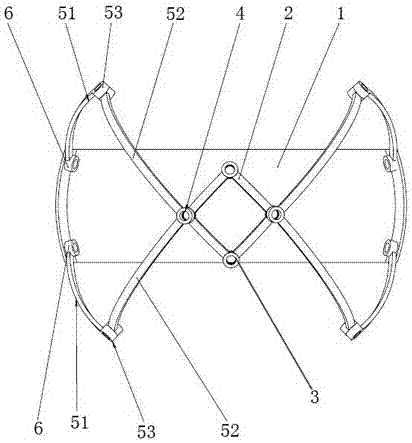
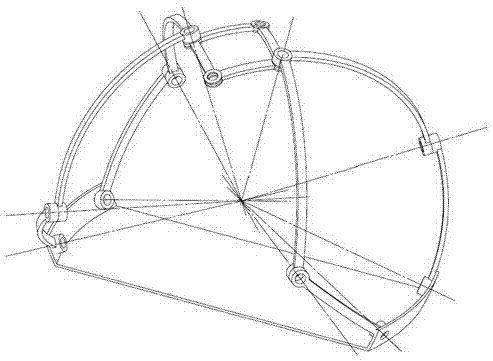
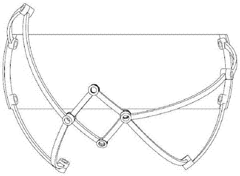
[0036] as attached figure 1 and 2 As shown, the present invention discloses a spherical parallel mechanism, including a machine base 1 and a moving platform 2, at least two sets of kinematic branch chains are arranged between the machine base 1 and the moving platform 2, and one set of kinematic branch chains includes two Active connecting rod 51 and two driven connecting rods 52; in the same group of kinematic branch chains, two active connecting rods 51 are rotationally connected with the base 1 through the rotating pair 6 of the base respectively, and one active connecting rod 51 is correspondingly passed through a connecting rod The rotary pair 53 is connected in rotation with a driven link 52, and the two driven links are connected in rotation through the output rotary pair 4. The connection po...


PUM


Abstract

A spherical parallel mechanism comprises a base and a moving platform; at least two groups of moving branch chains are arranged between the base and the moving platform; each group of the moving branch chains includes two driving connecting rods and two driven connecting rods; in the same group of the moving branch chains, the two driving connecting rods are rotationally connected with the base through base rotating pairs separately, each driving connecting rod is rotationally connected with one driven connecting rod through a connecting rod rotating pair correspondingly, the two driven connecting rods are rotationally connected through an output rotating pair, the connecting point of the two driven connecting rods is an output reference point, and the output reference point is rotationally connected with the moving platform through a moving platform rotating pair; and the axes of the base rotating pairs, the connecting rod rotating pairs, the output rotating pairs and the moving platform rotating pairs intersect at the same point. The spherical parallel mechanism is high in load capacity, high in positioning precision and large in working space, no driving motor is arranged on a moving component for the whole mechanism, and thus the structure is simple and light.

Description

technical field [0001] The invention relates to a spherical parallel mechanism. Background technique [0002] The spherical five-bar mechanism is a two-degree-of-freedom mechanism. It consists of five rods connected end to end through five revolving pairs, and the axes of all revolving pairs meet at one point (that is, the center of rotation). The output reference point of the mechanism is along the spherical surface. The two translational degrees of freedom of . Compared with the single-degree-of-freedom four-bar mechanism, it can complete more complex motion trajectories, and has the advantages of simple structure, flexible motion, and easy control. [0003] The parallel mechanism is a closed-loop mechanism in which the moving platform and the static platform are connected through at least two independent kinematic chains, have two or more degrees of freedom, and are driven in parallel. Compared with serial robots, parallel robots have the following advantages: small cum...

Claims


Application Information

Patent Timeline
Patent Type & Authority Applications(China)
IPC IPC(8): B25J9/00
CPCB25J9/003B25J9/0045B25J9/0048
Inventor 赵龙海陈强何永和姜纪波张延亮朱虹
Owner DONG GUAN AICREATE ROBOT TECH CO LTD
Why Eureka
Try Eureka