Eureka AIR delivers breakthrough ideas for toughest innovation challenges, trusted by R&D personnel around the world.

Cylinder body lining assembling tool

A technology for assembling tools and bushings, which is applied in the field of cylinder bushing assembling tools, can solve the problems of low installation efficiency, lack of limit devices, time-consuming and labor-consuming, etc., and achieve the advantages of not being easy to shake, ensuring installation accuracy and high work efficiency Effect

Inactive Publication Date: 2017-09-08
襄阳钛虎动力工程有限公司
View PDF8 Cites 0 Cited by
  • Summary
  • Abstract
  • Description
  • Claims
  • Application Information

AI Technical Summary

Problems solved by technology

[0002] In the production process of the engine body, there is a process of press-fitting the camshaft bushing, that is, to press the camshaft bushing into the specified position of the camshaft bottom hole of the engine body. In the past, the camshaft bushing was mostly pressed manually. The hammer strikes the mandrel for assembly. The installation phase and installation depth of the camshaft bushing on the cylinder block rely on human control and lack a limit device. It is difficult to guarantee the installation accuracy of the camshaft bushing on the cylinder block. The installation accuracy of the shaft bushing is poor; in addition, the installation of the camshaft bushing requires the cooperation of two producers. After these camshaft bushings are taken out of the diesel engine body with special tooling, they will be scrapped and cannot be reused. They must be reinstalled with new camshaft bushings. The entire installation process is time-consuming and labor-intensive, and the installation efficiency is low.

Method used


Image

  • Cylinder body lining assembling tool
  • Cylinder body lining assembling tool
  • Cylinder body lining assembling tool

Examples


Embodiment Construction

[0023] The present invention will be further described below in conjunction with the accompanying drawings and specific embodiments.

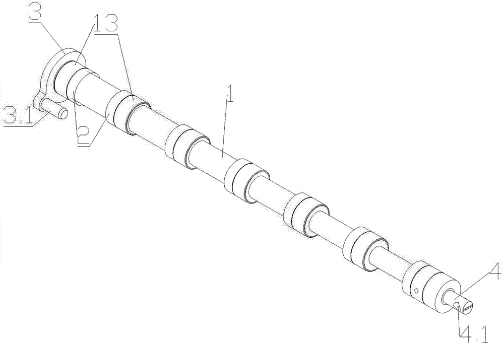
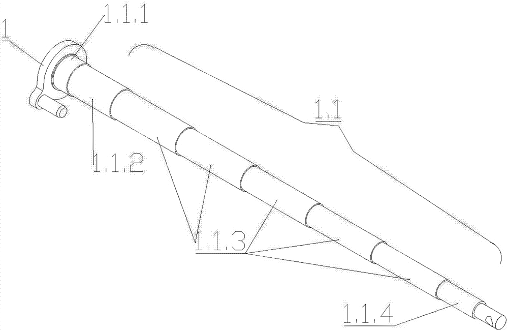
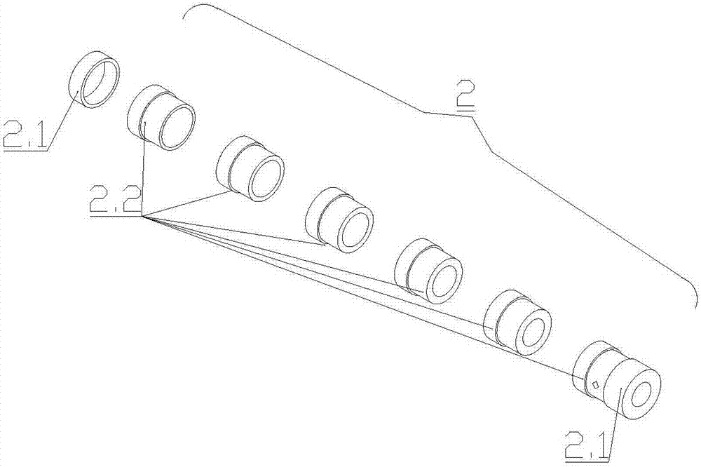
[0024] like Figure 1 to Figure 8 As shown, a cylinder bushing assembly tool includes an assembly pull rod, and the assembly pull rod includes a stepped shaft 1 and 8 spacer sleeves 2; the stepped shaft 1 includes 8 shaft bodies 1.1 with decreasing diameters in turn, The axes of body 1.1 are located on the same straight line, and the diameter difference between adjacent shaft bodies 1.1 is 4 mm; shaft body 1.1 includes positioning shaft body 1.1.1, top shaft body 1.1.2, tail shaft body 1.1.4 and top shaft body 5 middle shaft bodies 1.1.3 between the body 1.1.2 and the tail shaft body 1.1.4; the axial lengths of the top shaft body 1.1.2, the tail shaft body 1.1.4 and each middle shaft body 1.1.3 and the corresponding The distance between each limit baffle plate 12 of the cylinder block 10 camshaft hole 11 matches; the axial width of the positio...


PUM


Abstract

The invention discloses a cylinder body lining assembling tool which comprises an assembling pull rod. The assembling pull rod comprises a stepped shaft and a plurality of limiting sleeves. The stepped shaft comprises a plurality of shaft bodies with the diameters gradually decreased. The axial lengths of the shaft bodies are matched with the distance between limiting baffles of a corresponding cylinder body cam shaft hole. The diameter difference value of every two adjacent shaft bodies is 2-6 mm. The limiting sleeves are located on the corresponding shaft bodies. The top of the stepped shaft is provided with a positioning end face. The positioning end face is provided with a positioning pin. The tail end of the stepped shaft is provided with a connection rod with a pin hole. According to the assembling tool, the stepped shaft and the limiting sleeves matched with the shaft bodies of the stepped shaft are adopted, hydraulic equipment is utilized for completing installation of all linings in one cam shaft hole at a time, operation is efficient, and the precision is high.

Description

technical field [0001] The invention relates to an engine assembly auxiliary tool, in particular to a cylinder liner assembly tool. Background technique [0002] In the production process of the engine body, there is a process of press-fitting the camshaft bushing, that is, to press the camshaft bushing into the specified position of the camshaft bottom hole of the engine body. In the past, the camshaft bushing was mostly pressed manually. The hammer strikes the mandrel for assembly. The installation phase and installation depth of the camshaft bushing on the cylinder block rely on human control and lack a limit device. It is difficult to guarantee the installation accuracy of the camshaft bushing on the cylinder block. The installation accuracy of the shaft bushing is poor; in addition, the installation of the camshaft bushing requires the cooperation of two producers. After these camshaft bushings are taken out from the diesel engine body by special tooling, they will be ...

Claims


Application Information

Patent Timeline
Patent Type & Authority Applications(China)
IPC IPC(8): B25B27/02B23P19/027
CPCB23P19/027B25B27/026
Inventor 许雄兵霍大华李国照
Owner 襄阳钛虎动力工程有限公司
Why Eureka
Eureka Blog
Learn More