
Message pushing control method and device

A message push and control device technology, applied in the field of communication, can solve the problems of high push pressure on the server, achieve the effects of reducing pressure and load, improving system performance, and reducing delay

Inactive Publication Date: 2017-09-05
NUBIA TECHNOLOGY CO LTD
View PDF5 Cites 13 Cited by
  • Summary
  • Abstract
  • Description
  • Claims
  • Application Information

AI Technical Summary

Problems solved by technology

[0005] The main purpose of the present invention is to propose a message push control method and device, aiming to solve the problem of high push pressure on the server and push delay in the prior art when the SNS application dynamic message is pushed

Method used


Image

  • Message pushing control method and device
  • Message pushing control method and device
  • Message pushing control method and device

Examples


Embodiment Construction

[0049] It should be understood that the specific embodiments described here are only used to explain the present invention, not to limit the present invention.

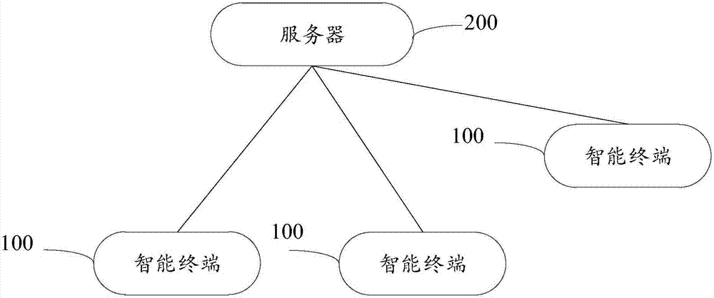
[0050] A smart terminal implementing various embodiments of the present invention will now be described with reference to the accompanying drawings. In the following description, use of suffixes such as 'module', 'part' or 'unit' for denoting elements is only for facilitating description of the present invention and has no specific meaning by itself. Therefore, "module" and "component" may be used mixedly. figure 1 It is a schematic structural diagram of a system for implementing message push control methods in various embodiments of the present invention.

[0051] The message push control system includes multiple smart terminals 100 (only three are shown in the figure) and a server 200 .

[0052] In the present invention, the target social application is installed on the smart terminal 100 , and the user can log in...


PUM


Abstract

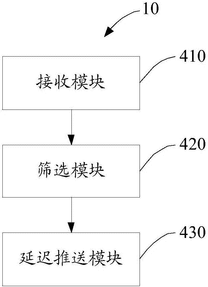
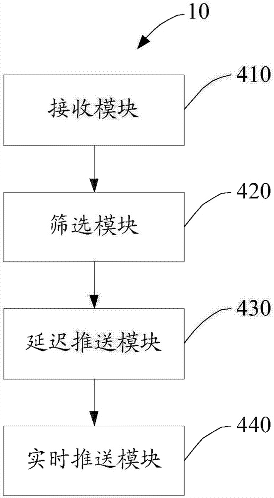
The invention discloses a message pushing control method and device. The device comprises a receiving module, a screening module and a pushing delay module; the receiving module is used for querying a subscription list subscribing account numbers of users when dynamic messages published by the users through a target social application installed on an intelligent terminal are received; the screening module is used for selecting different types of account numbers from the subscription list, wherein the account numbers comprise the inactive account numbers; and the pushing delay module is used for starting to push the dynamic messages to inboxes of the inactive account numbers when a preset time is up. Accordingly, different pushing strategies are adopted for different users, pushing delay is adopted for the inactive users, pushing is conducted at the fixed time, the pushing pressure is greatly reduced, the real-time pressure and load of a server are reduced, resource waste is avoided, the system performance is improved, and meanwhile the delay phenomenon generated during the real-time pushing process of the active users can be reduced.

Description

technical field [0001] The present invention relates to the technical field of communication, in particular to a message push control method and device for social applications. Background technique [0002] SNS system, also known as SNS program, SNS software, social network system, is a program and service for building social networking sites. A complete SNS system usually has multiple functional modules such as log, photo album, sharing, group, mood, voting, etc., and the functional application can be extended through the plug-in mechanism and open application programming interface. The most important of these is the Feed system (message distribution system). The Feed system is the core and the most complex part of SNS applications, mainly involving the push and subscription management of dynamic messages published between different users of social applications. [0003] At present, the mainstream adopts the push mode to design the distribution system. The so-called push m...

Claims


Application Information

Patent Timeline
IPC IPC(8): H04L12/58H04L29/08
CPCH04L51/214H04L51/52H04L67/55
Inventor 刘孟焱
Owner NUBIA TECHNOLOGY CO LTD
Learn More