
Intelligent modular low-voltage distribution cabinet

A technology of intelligent modules and power distribution cabinets, applied in the direction of electrical components, substation/switch layout details, etc., can solve the problems of complicated secondary wiring, long customer delivery period, small installation capacity, etc., and achieve convenient monitoring and management, safe and reliable connection , the effect of high security level

Active Publication Date: 2017-09-05
广西华超电气有限公司
View PDF12 Cites 1 Cited by
  • Summary
  • Abstract
  • Description
  • Claims
  • Application Information

AI Technical Summary

Problems solved by technology

[0002] At present, there are many types of low-voltage power distribution cabinets on the market, such as: fixed cabinets, drawer cabinets, fixed partition cabinets, etc. However, these low-voltage power distribution cabinets have their own advantages and disadvantages. Although fixed cabinets are relatively cheap and flexible to install, However, its safety protection level is low, the operation is dangerous, and it is impossible to repair and maintain a single switch. There is no interval between the circuits, and the fault range is easy to expand. There is no standard for the secondary wiring. Although the drawer cabinet can be installed flexibly and can be maintained online, its The installation capacity is small, the primary and secondary wiring is complicated, and the fixed partition cabinet also has the problem of complicated primary and secondary wiring. At the same time, the above-mentioned various low-voltage power distribution cabinets have a large number of electrical components, without a unified standardized design, and the assembly and replacement are complicated. , the delivery time to the customer is long, it is easy to affect the progress of the customer's project, and it is also quite insufficient in terms of intelligence, which is inconvenient to manage

Method used

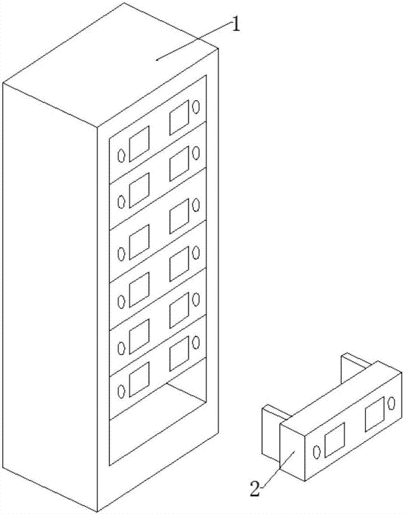

Image

  • Intelligent modular low-voltage distribution cabinet
  • Intelligent modular low-voltage distribution cabinet
  • Intelligent modular low-voltage distribution cabinet

Examples


Embodiment Construction

[0029] The present invention will be further described in detail below in conjunction with the accompanying drawings, so that those skilled in the art can implement it with reference to the description.

[0030] It should be noted that, in the description of the present invention, the terms "horizontal", "vertical", "upper", "lower", "front", "rear", "left", "right", "vertical", The orientation or positional relationship indicated by "horizontal", "top", "bottom", "inner", "outer", etc. is based on the orientation or positional relationship shown in the drawings, and is only for the convenience of describing the present invention and simplifying the description, and It is not to indicate or imply that the device or element referred to must have a particular orientation, be constructed in a particular orientation, or operate in a particular orientation, and thus should not be construed as limiting the invention.

[0031] The present invention provides an intelligent modular low...


PUM


Abstract

The invention discloses an intelligent modular low-voltage distribution cabinet which comprises a plurality of circuit elements. Incoming ends and outgoing ends of the circuit elements are designed into blocky shells integrally connected with the circuit elements, three parallel first through holes are formed in each shell, metal internal threads connected with three-phase wire terminals of the circuit elements are coaxially arranged in the first through holes, and the first through holes in the outgoing end of one circuit element and the first through holes in the incoming end of another circuit element are vertically aligned and then serially connected by screws. Various circuit elements are designed to be standard modular, circuit connection portions are only provided with copper plates and a small quantity of communication cables, secondary connection is omitted, connection is safer and more reliable, and maintenance is more facilitated. Besides, if load increase is found in the running process, capacity can be rapidly expanded, and the maximum loop number of the single cabinet is large.

Description

technical field [0001] The invention relates to the field of electric power equipment. More specifically, the present invention relates to an intelligent modular low-voltage power distribution cabinet. Background technique [0002] At present, there are many types of low-voltage power distribution cabinets on the market, such as: fixed cabinets, drawer cabinets, fixed partition cabinets, etc. However, these low-voltage power distribution cabinets have their own advantages and disadvantages. Although fixed cabinets are relatively cheap and flexible to install, However, its safety protection level is low, the operation is dangerous, and it is impossible to repair and maintain a single switch. There is no interval between the circuits and the fault range is easy to expand. There is no standard for the secondary wiring. Although the drawer cabinet is flexible in installation and can be maintained online, its The installation capacity is small, the primary and secondary wiring i...

Claims


Application Information

Patent Timeline
Patent Type & Authority Applications(China)
IPC IPC(8): H02B1/32H02B1/044
CPCH02B1/044H02B1/32
Inventor 黄金超金锋
Owner 广西华超电气有限公司
Learn More