Optical module

An optical module and laser technology, applied in the field of optical communication, can solve the problems of residual stress, output optical power change of optical transmitter, and 50 large optical multiplexing components, so as to achieve the effect of speeding up and avoiding micro-deformation

Inactive Publication Date: 2017-09-05
HISENSE BROADBAND MULTIMEDIA TECH
View PDF5 Cites 3 Cited by
  • Summary
  • Abstract
  • Description
  • Claims
  • Application Information

AI Technical Summary

Problems solved by technology

However, the inventor found in the process of realizing the present invention that since the optical multiplexing component 50 is fixed on the base 80 by glue, there is a difference between the thermal expansion coefficient of the material of the optical multiplexing component 50 and the thermal expansion coefficient of the above-mentioned glue, and the difference in the above-mentioned thermal expansion coefficient After the glue used to mount the optical multiplexing component 50 is cured, it will bring a lot of residual stress inside the optical multiplexing component 50
Moreover, the existence of the above-mentioned residual stress causes the polarization direction of the light beam passing through the optical multiplexing component 50 to change, and when the polarization direction of the light beam changes, the optical power of the light beam passing through the isolator will change, thereby causing light emission The change of output optical power of the device affects the quality of data communication

Method used


Image

  • Optical module
  • Optical module
  • Optical module

Examples


Embodiment Construction

[0024] Reference will now be made in detail to the exemplary embodiments, examples of which are illustrated in the accompanying drawings. When the following description refers to the accompanying drawings, the same numerals in different drawings refer to the same or similar elements unless otherwise indicated. The implementations described in the following exemplary examples do not represent all implementations consistent with the present invention. Rather, they are merely examples of apparatuses and methods consistent with aspects of the invention as recited in the appended claims.

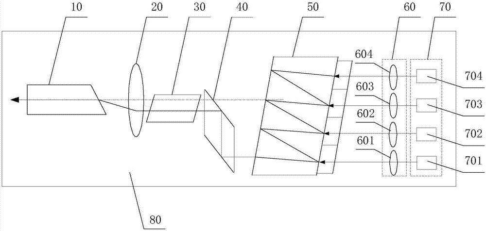
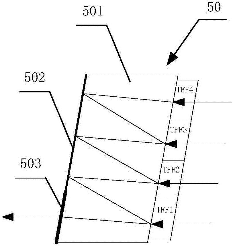
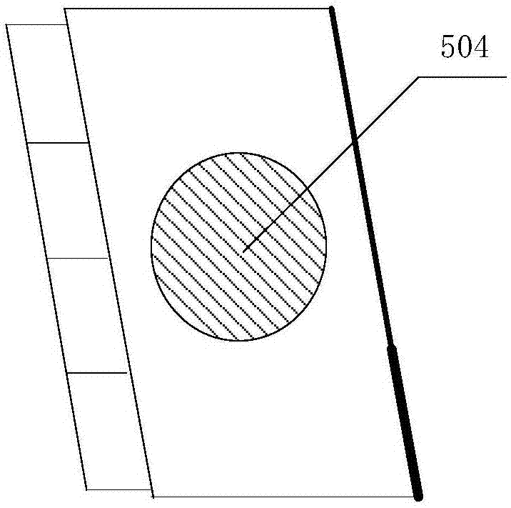
[0025] During the packaging process of the optical module, the optical multiplexing component based on the thin film filter technology is directly fixed on the base of the optical module by glue. In the prior art, the glue will cover the entire bottom area of ​​the optical multiplexing component during fixing. However, due to the difference between the thermal expansion coefficient of the optica...


PUM


Abstract

The invention relates to an optical module. To be specific, the optical module is structured in such a way that an optical multiplexing assembly is adopted, a protruding structure is designed on a pedestal used for fixing the optical multiplexing assembly, and the protruding structure is used for controlling the coverage area of glue at the bottom of the optical multiplexing assembly after the surface mounting of the optical multiplexing assembly. In this way, during surface mounting of the optical multiplexing assembly, the coverage area of glue on the optical multiplexing assembly can be well controlled even if a lot of glue is utilized. Therefore, residual stress acting on the optical multiplexing assembly after solidification of the glue can be controlled effectively, and the stability of optical power output by an optical emitter in the optical module is ensured.

Description

technical field [0001] The invention relates to the technical field of optical communication, in particular to an optical module. Background technique [0002] Optical transceiver integrated module, referred to as optical module, is a standard module in the field of optical communication equipment. A standard optical module usually includes devices such as an optical transmitter, an optical receiver, a microprocessor, and a laser driver; among them, the optical transmitter includes a laser, an isolator, an optical fiber adapter, and an optical passive that couples the light emitted by the laser into the optical fiber adapter. Components used to convert electrical signals into optical signals. Furthermore, in the field of high-speed data communication, in order to ensure long-distance and high-speed transmission of data, the currently commonly used solution is to multiplex multiple optical signals of different wavelengths into one optical signal for transmission in a single ...

Claims


Application Information

Patent Timeline
Patent Type & Authority Applications(China)
IPC IPC(8): G02B6/42
CPCG02B6/4296G02B6/4239
Inventor 唐永正丁良云
Owner HISENSE BROADBAND MULTIMEDIA TECH
Why Eureka
Try Eureka