Rotary valve

A technology for turning off fans and air ducts, applied in the separation of dispersed particles, chemical instruments and methods, separation methods, etc., can solve the problems of small wind speed, large wind speed, and unclean separation of small particles, and achieve the effect of prolonging time and improving efficiency.

Active Publication Date: 2017-09-05
JIANGSU WOLVES MACHINERY
View PDF6 Cites 5 Cited by
  • Summary
  • Abstract
  • Description
  • Claims
  • Application Information

AI Technical Summary

Problems solved by technology

[0002] When the existing shut-off fan separates the particles, it is generally a one-stage type, which will cause two situations in the separation process of the particles, one is that the separation wind speed is too high, and the large particles are taken away directly; the other is the separation wind speed Too small, the separation of small particles is not clean

Method used


Image

  • Rotary valve
  • Rotary valve

Examples


Embodiment Construction

[0021] The specific implementation manners of the present invention will be further described in detail below in conjunction with the accompanying drawings and embodiments. The following examples are used to illustrate the present invention, but are not intended to limit the scope of the present invention.

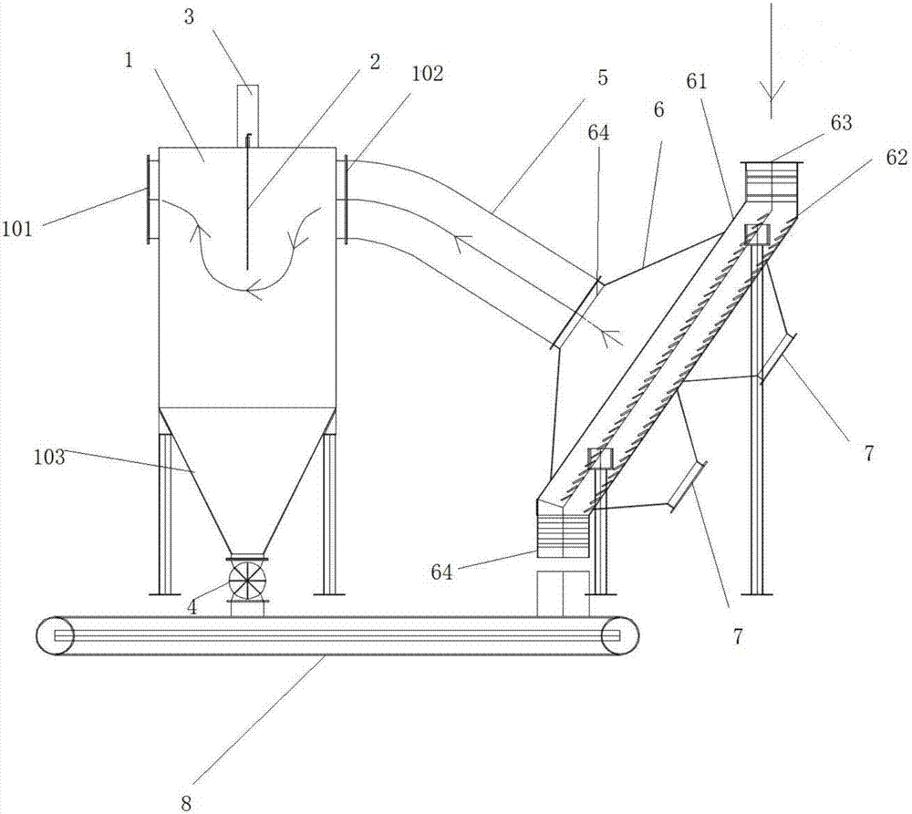
[0022] see figure 1 with figure 2 A shut-off fan described in a preferred embodiment of the present invention includes a depowdering device 6, an air duct 5 and a settling dust removal device 1, one end of the air duct 5 is connected to the discharge port 64 of the depowdering device 6, One end is connected to the sedimentation inlet 102 of the sedimentation dust removal device 1;

[0023] The depowdering device 6 includes a depowdering passage 61 arranged obliquely, the top of the depowdering passage 61 is provided with a feed port 63, the bottom is provided with a discharge port 64, and the upper side of the depowdering passage 61 is provided with a funnel Shaped con...


PUM


Abstract

The invention relates to a rotary valve. The rotary valve comprises a dust removal device (6), an air pipe (5) and a sedimentation dedusting device (1). The dust removal device (6) comprises an inclined dust removal passage (61), and the top of the dust removal passage (61) is provided with a feeding port (63) while the top of the dust removal passage (61) is provided with a discharging port (64). The upper side of the dust removal passage (61) is provided with a funnel shaped connection port which is connected with the discharging port (64), and a plurality of air adjusting valves (7) are arranged on the lower side of the dust removal passage (61). The sedimentation dedusting device (1) is a cubic shell with the bottom connected with a 'V'-shaped funnel (103), the lateral surface of one end of the sedimentation dedusting device (1) is provided with a sedimentation outlet (101) while the lateral surface of the other end of the sedimentation dedusting device (1) is provided with a sedimentation inlet (102), a housing (3) is arranged outside the sedimentation dedusting device (1), and the sedimentation outlet (101) is connected with an external dust collector. The rotary valve is simple in structure and high in dedusting efficiency.

Description

technical field [0001] The invention relates to a dust removal device, in particular to a multi-stage dust removal shut-off fan. Background technique [0002] When the existing shut-off fan separates the particles, it is generally a one-stage type, which will cause two situations in the separation process of the particles, one is that the separation wind speed is too high, and the large particles are taken away directly; the other is the separation wind speed If it is too small, the separation of small particles will not be clean. [0003] In view of the above-mentioned defects, the designers are actively researching and innovating in order to create a novel structure of shut-off fan, so that it has more industrial utilization value. Contents of the invention [0004] In order to solve the above technical problems, the object of the present invention is to provide a shut-off fan capable of removing a lot of dust. [0005] Technical scheme of the present invention is as f...

Claims


Application Information

Patent Timeline
Patent Type & Authority Applications(China)
IPC IPC(8): B01D45/02B01D45/08
CPCB01D45/02B01D45/08
Inventor 冯华
Owner JIANGSU WOLVES MACHINERY
Why Eureka
Try Eureka