
Formwork structure of shear wall corner joint, shear wall cast-in-situ system and construction method

A technology of shear walls and corners, applied in the direction of formwork/formwork/work frame, connection parts of formwork/formwork/work frame, walls, etc., can solve the damage of exterior panels, poor integrity of exterior tiles, and beautiful structure Poor performance and other problems, to achieve the effect of simplifying construction engineering, firm and reliable connection nodes, and ensuring integrity

Active Publication Date: 2017-09-01
CHINA CONSTR FIRST DIV GROUP CONSTR & DEV
View PDF7 Cites 6 Cited by
  • Summary
  • Abstract
  • Description
  • Claims
  • Application Information

AI Technical Summary

Problems solved by technology

[0003] The present invention proposes a formwork structure for corner joints of a shear wall, a cast-in-place system and a construction method for a shear wall, and aims to solve the problems of easy damage to exterior panels, poor integrity of exterior bricks, and poor structural aesthetics during the construction of traditional formwork structures technical problem

Method used


Image

  • Formwork structure of shear wall corner joint, shear wall cast-in-situ system and construction method
  • Formwork structure of shear wall corner joint, shear wall cast-in-situ system and construction method
  • Formwork structure of shear wall corner joint, shear wall cast-in-situ system and construction method

Examples


Embodiment Construction

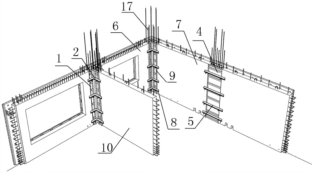
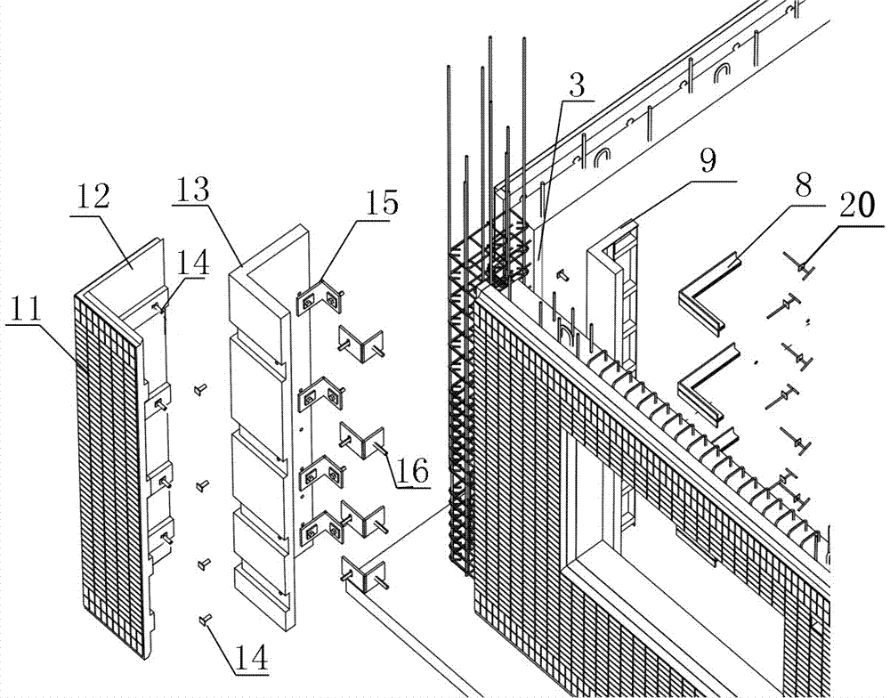
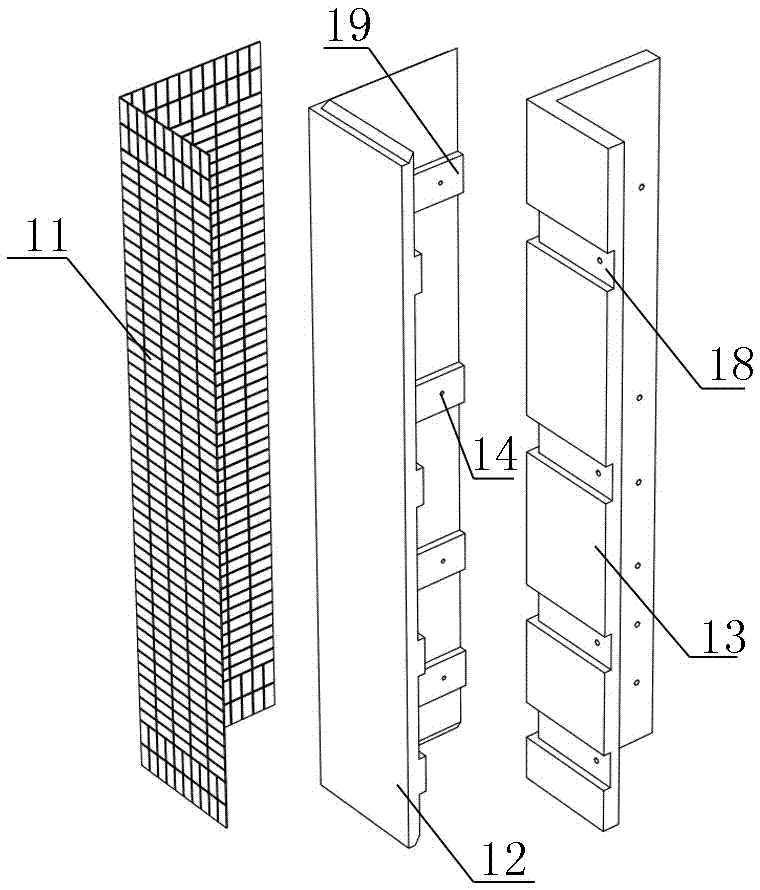
[0038] Such as Figure 1-3 As shown, the formwork structure of the corner joint of the shear wall is set between the transverse prefabricated exterior wall 6 and the longitudinal prefabricated exterior wall 7 on both sides of the corner of the prefabricated shear wall, including The corner outer formwork, the corner inner formwork 9 installed on the inside of the corner of the shear wall, and the corner back flute 8 installed on the inside of the corner inner formwork 9 at intervals along the vertical parallel; and the longitudinal side; the corner outer template is a PCF board, including heat preservation board 13, outer leaf wall board 12 and exterior facing brick 11 arranged in sequence from inside to outside; the outer surface of the heat preservation board 13, along Horizontal through grooves 18 are provided at vertical parallel intervals; horizontally through concrete ribs 19 are provided on the inner side of the outer leaf wall panels 12 at positions corresponding to th...


PUM


Abstract

A formwork structure of a shear wall corner joint, a shear wall cast-in-situ system and a construction method are disclosed. The formwork structure of the shear wall corner joint comprises a corner external formwork, a corner internal formwork and corner dorsal bars, wherein the corner external formwork is mounted on the outer portion of a shear wall corner, the corner internal formwork is mounted on the inner side of the shear wall corner, and the corner dorsal bars are parallelly mounted on the inner side of the corner internal formwork at intervals in the vertical direction; the horizontal section of the corner external formwork is in an L shape; the corner external formwork is a PCF slab, and comprises an insulation board, an external leaf wall board and external face bricks which are sequentially arranged from inside to outside; horizontally-through grooves are parallelly formed in the outer side surface of the insulation board at intervals in the vertical direction; horizontally-penetrating concrete ribs are arranged on the positions, corresponding to the grooves, on the inner side surface of the external leaf wall board; and the external leaf wall board is tightly attached to the outer side surface of the insulation board, and the concrete ribs on the external leaf wallboard are embedded in the grooves correspondingly. According to the formwork structure of the shear wall corner joint and the shear wall cast-in-situ system and the construction method, the technical problems that when a traditional formwork structure construction is conducted, an external veneer is prone to being damaged, the integrality of external face bricks is poor, and structure attractiveness is poor are solved.

Description

technical field [0001] The present invention relates to a formwork structure of a shear wall corner node, a cast-in-place system of a shear wall and a construction method, in particular to a construction method of a formwork structure of a prefabricated shear wall system for installing exterior facing bricks Pack. Background technique [0002] The prefabricated shear wall structure has developed vigorously in recent years. At present, the commonly used construction method is to use prefabricated components for production and processing in the component factory, and then carry out hoisting construction operations at the construction site. Some projects use exterior facing bricks as the exterior decoration layer of the building, while the exterior facing bricks can be prefabricated on the wall surface together with the prefabricated exterior wall to ensure the integrity of the facing bricks and the outer leaf wall panels. Facing bricks, when there are windows and wall holes o...

Claims


Application Information

Patent Timeline
Patent Type & Authority Applications(China)
IPC IPC(8): E04G11/06E04G17/065E04B2/00
CPCE04B2/00E04G11/06E04G17/0654Y02B30/90Y02A30/00
Inventor 谢方新袁齐尹硕党小虎余鹏孔祥忠李浩姜伟李贝吕雪源
Owner CHINA CONSTR FIRST DIV GROUP CONSTR & DEV
Learn More