
Highly anti-clogging buried pressure compensation drip irrigation irrigator

A pressure compensation and irrigation technology, applied in watering devices, climate change adaptation, gardening, etc., can solve problems such as inability to guarantee flow uniformity and consistency, clogging of irrigation devices, etc., to avoid sediment and root invasion, avoid The effect of suction clogging, overcoming unevenness and inconsistency

Inactive Publication Date: 2017-09-01
GANSU DAYU WATER SAVING +1
View PDF3 Cites 3 Cited by
  • Summary
  • Abstract
  • Description
  • Claims
  • Application Information

AI Technical Summary

Problems solved by technology

At present, the flat emitters used in domestically produced inlaid drip irrigation emitters are basically non-pressure-compensated emitters. When the water flow pressure changes, the flow rate of the emitters will change accordingly, especially in hilly areas, which cannot be guaranteed. Uniformity and Consistency of Flow
However, when the emitter is used under the ground, there are often phenomena such as negative pressure mud suction and root invasion, and the emitter is very prone to blockage. It is difficult for conventional drip irrigation emitters to be used underground. Therefore, the design can be buried and used. Drip irrigation emitters with compensation and good anti-clogging function are necessary

Method used


Image

  • Highly anti-clogging buried pressure compensation drip irrigation irrigator
  • Highly anti-clogging buried pressure compensation drip irrigation irrigator
  • Highly anti-clogging buried pressure compensation drip irrigation irrigator

Examples


Embodiment Construction

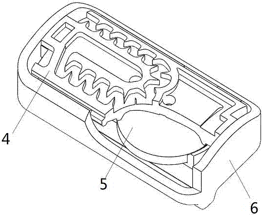
[0024] Such as Figure 1~7 As shown, a highly anti-clogging underground pressure-compensated drip irrigation emitter includes an inlaid pressure-compensated dripper 2 bonded to the inner wall of a PE hose 1 by hot-melting. The PE hose 1 is provided with a water outlet 3 along a narrow slit perpendicular to the cross section of the pipe. The built-in pressure compensation dripper 2 includes an upper cover 4 and a lower casing 6 connected together and an elastic membrane 5 installed between the upper cover 4 and the lower casing 6 . The elastic diaphragm 5 refers to a disc made of silicon rubber with a diameter of 8.8 mm and a thickness of 1 mm.

[0025] The front of the upper cover sheet 4 is provided with a cylindrical upper cover sheet welding surface 13, and the flanks on both sides are respectively provided with an assembly card platform 14, and the back is flat; The main channel 8 and the water outlet buffer chamber 11; one end of the main channel 8 is provided with a ma...


PUM

PropertyMeasurementUnit
Diameteraaaaaaaaaa
Thicknessaaaaaaaaaa

Abstract

The invention relates to a highly anti-clogging buried pressure compensation drip irrigation irrigator. The irrigator comprises an inserted pressure compensation dropper adhered to the inner wall of a PE hose through hot melting. A narrow slit water outlet is formed in the PE hose; the inserted pressure compensation dropper comprises an upper cover piece, a lower shell and an elastic film; an upper cover piece cementing surface and an assembled clamping table are arranged on the front of the upper cover piece, and the back of the upper cover piece is a flat plane; a main flow channel and an effluent buffer chamber are formed in the upper cover piece cementing surface; a holed supporting boss is formed in the effluent buffer chamber; a supporting boss and a screening positioning table as well as a recessed area and a compensation chamber water sealing ring are arranged on the back of the upper cover piece; the compensation chamber water sealing ring and the elastic film form a compensation chamber; a compensation chamber water inlet, a limiting boss and an overflow tank are arranged on the compensation chamber; a gridded filter window and a dropper screening tank are arranged on the front of the lower shell, and a filter window water inlet and a lower shell cementing surface are formed in the back of the lower shell; a suck-back prevention water sealing ring and a film mounting tank for mounting the elastic film are arranged on the filter window water inlet; and a mounting positioning table and an assembling fastener are arranged on the back of the lower shell. The irrigator disclosed by the invention is excellent in pressure compensation and anti-clogging effects.

Description

technical field [0001] The invention relates to the technical field of agricultural water-saving drip irrigation, in particular to an underground pressure-compensated drip irrigation emitter with high anti-clogging resistance. Background technique [0002] As an emerging water-saving irrigation technology, drip irrigation has developed rapidly in my country in recent years. The key equipment of the drip irrigation system is to evenly and stably drip the pressure water into the soil after dissipating energy, so as to keep the crop soil in an optimal water content state. At present, the flat emitters used in domestically produced inlaid drip irrigation emitters are basically non-pressure-compensated emitters. When the water flow pressure changes, the flow rate of the emitters will change accordingly, especially in hilly areas, which cannot be guaranteed. Uniformity and consistency of flow. However, when the emitter is used under the ground, there are often phenomena such as ...

Claims


Application Information

Patent Timeline
IPC IPC(8): A01G25/06
CPCA01G25/06A01G2025/006Y02A40/22
Inventor 徐希彬贾俊喜薛瑞清李伟王飞
Owner GANSU DAYU WATER SAVING
Learn More