
Head up display device

A head-up display device and technology for displaying light, which is applied in the direction of transportation and packaging, instruments, polarizing components, etc., can solve the problems of large overall size and high price of head-up display devices, and achieve the effect of improving the strength of heat resistance

Inactive Publication Date: 2017-08-29
NIPPON SEIKI CO LTD
View PDF6 Cites 4 Cited by
  • Summary
  • Abstract
  • Description
  • Claims
  • Application Information

AI Technical Summary

Problems solved by technology

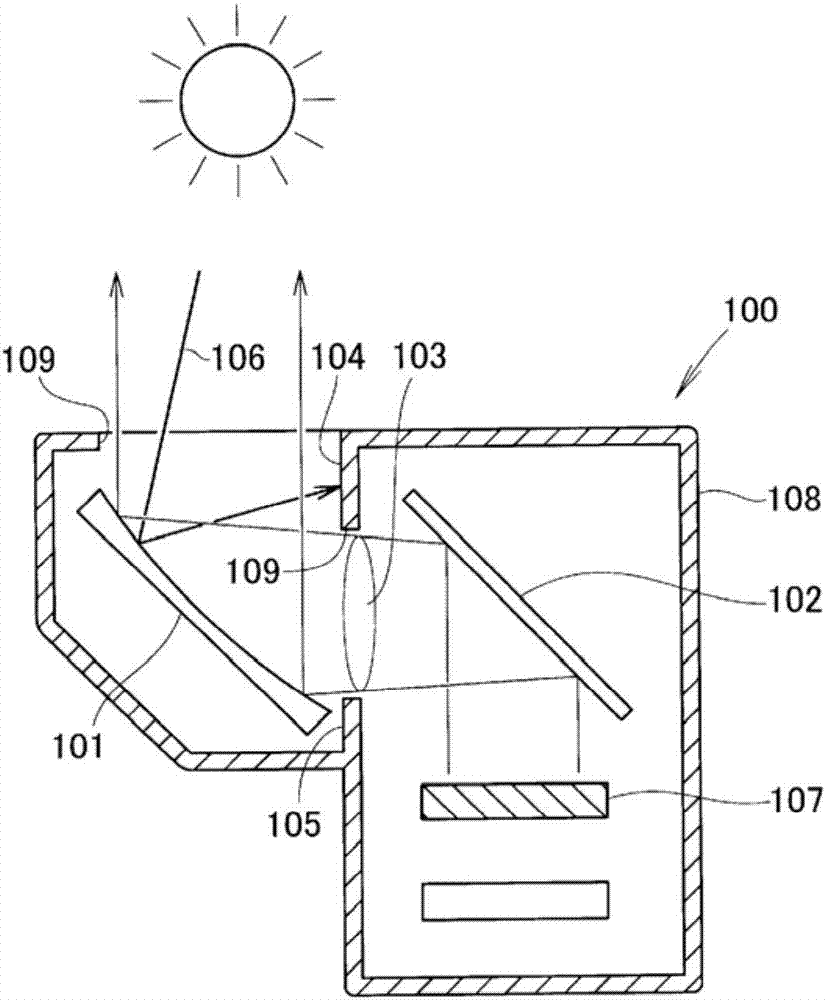
However, since the reflective polarizing film (21) and the glass substrate (22) are necessary, there is a concern that the price of the head-up display device is high and the overall size is large.

Method used


Image

  • Head up display device
  • Head up display device
  • Head up display device

Examples


Embodiment 1

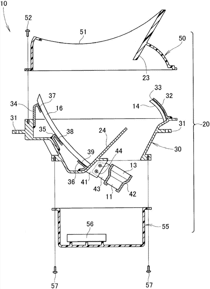
[0070] picture image 3 As shown, in the head-up display device 10, the housing 20 is composed of an intermediate frame 30, an upper cover 50, and a lower cover 55. The intermediate frame 30 supports the first and second concave mirrors 14, 16 and includes a second shield part 24 , the upper cover 50 is installed on the middle bracket 30 , including the first shielding portion 23 , and the lower cover 55 is installed under the middle bracket 30 .

[0071] The intermediate bracket 30 is an aluminum die-cast, has mounting flanges 31 and 31 on its outer periphery, and has a second shielding portion 24 extending obliquely upward inside the aluminum die-cast.

[0072] For example, a stay 32 is welded to the intermediate bracket 30 , and the first concave mirror 14 is fixed to the stay 32 via an adhesive layer 33 . In addition, the second concave mirror 16 is fixed to the stays 34 to 36 welded to the inner surface of the intermediate bracket 30 via adhesive layers 37 to 39 .

[00...

Embodiment 2

[0095] refer to Figure 8 . Embodiment 2 of the present invention will be described below with reference to the accompanying drawings. Figure 8 The cross-sectional structure of the head-up display device of Example 2 is shown. Figure 8 corresponding to the above Figure 4 to express.

[0096] In the head-up display device 10A of the second embodiment, the metal plate 71 is provided on the upper surface of the first shielding portion 23 . Regarding other basic structures, it is the same as that of the head-up display device 10 of Embodiment 1 (refer to Figure 4 )common. For parts common to those in Embodiment 1, reference numerals are used, and specific descriptions are omitted.

[0097] The upper cover 50A is a resin molded product, for example, a mixed resin material of polycarbonate and polyethylene terephthalate (PET) can be used.

[0098] The raw material of the metal plate 71 can be aluminum or aluminum alloy.

[0099] In addition, the density of the resin cons...


PUM


Abstract

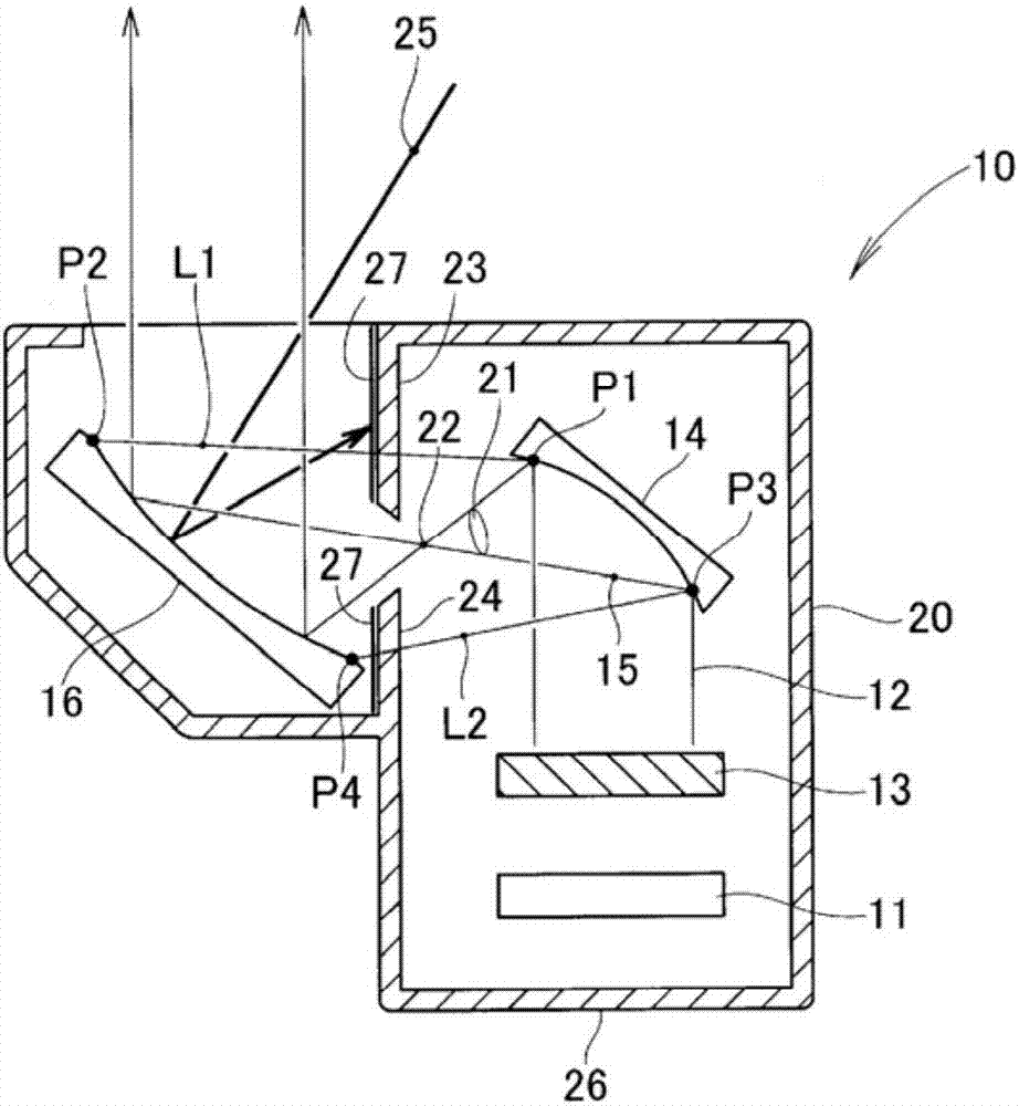
The problem addressed by the present invention is to provide a head up display device capable of counteracting sunlight without using a shutter or a reflection type polarizing film. A first concave mirror (14) has a curvature to cause the reflected display light (15) to intersect vertically before reaching a second mirror (16), and a second concave mirror (16) serves to reflect the received display light. A case (20) is provided with a first shield (23) and a second shield (24) extending near an intersecting point (22) to sandwich a light path (21) between the first and second concave mirrors (14, 16). The first and second shields (23, 24) can block external light (25) entering into the case (20) from outside the case (20) and proceeding toward the first concave mirror (14) after being reflected from the second concave mirror (16).

Description

technical field [0001] The present invention relates to a head-up display device that implements countermeasures against sunlight. Background technique [0002] The driver of the vehicle looks ahead through the windshield and drives while looking at the gauges on the instrument panel. That is, the gaze moves to the front and bottom instrument classes. If the instruments can be viewed while looking ahead, there is no movement of the line of sight, and improvement in drivability can be expected. From this point of view, head-up display devices have been developed for practical use. As a prior art related to a head-up display device, there is a technology disclosed in Patent Document 1. As shown in FIG. [0003] like Patent Document 1 figure 1 As shown, image light emitted upward from the HUD display (2) (numbers in parentheses indicate reference numbers described in Patent Document 1. The same applies below) hits the inner surface of the windshield (5) and is reflected , ...

Claims


Application Information

Patent Timeline
Patent Type & Authority Applications(China)
IPC IPC(8): G02B27/01B60K35/00
CPCB60K35/00G02B5/30G02B2027/0118G02B27/0101B60K35/23B60K35/213B60K35/415B60K2360/334B60K35/50G02B27/01G02B1/14G02B1/11G02B5/10G02B27/0149G02B2027/0152
Inventor 山添尚广川拓郎
Owner NIPPON SEIKI CO LTD
Learn More