
Pressure sensor and pressure sensor module

A technology of pressure sensor and substrate, which is applied in the direction of measuring fluid pressure, measuring fluid pressure through electromagnetic components, instruments, etc. It can solve the problems of unstable electrical characteristics of pressure sensors and the inability of the shell to support the pressure sensor stably, and achieve a reliable waterproof structure. , Stable bonding, and the effect of inhibiting wetting and expansion

Inactive Publication Date: 2017-08-29
THE FUJIKURA CABLE WORKS LTD
View PDF8 Cites 5 Cited by
  • Summary
  • Abstract
  • Description
  • Claims
  • Application Information

AI Technical Summary

Problems solved by technology

[0009] Conventionally, when the lead part on the lower surface side of the pressure sensor is joined to the printed circuit board by soldering, the solder may wet and spread excessively on the lead part on the lower surface side of the base body.
And due to excessive wetting of the expanded solder, there are cases where the housing cannot stably support the lower surface of the pressure sensor
Also, when the solder wets and spreads up to the lead wires on the side of the pressure sensor, the lead wires on the side come into contact with the case, and the electrical characteristics of the pressure sensor become unstable.

Method used


Image

  • Pressure sensor and pressure sensor module
  • Pressure sensor and pressure sensor module
  • Pressure sensor and pressure sensor module

Examples


no. 1 approach

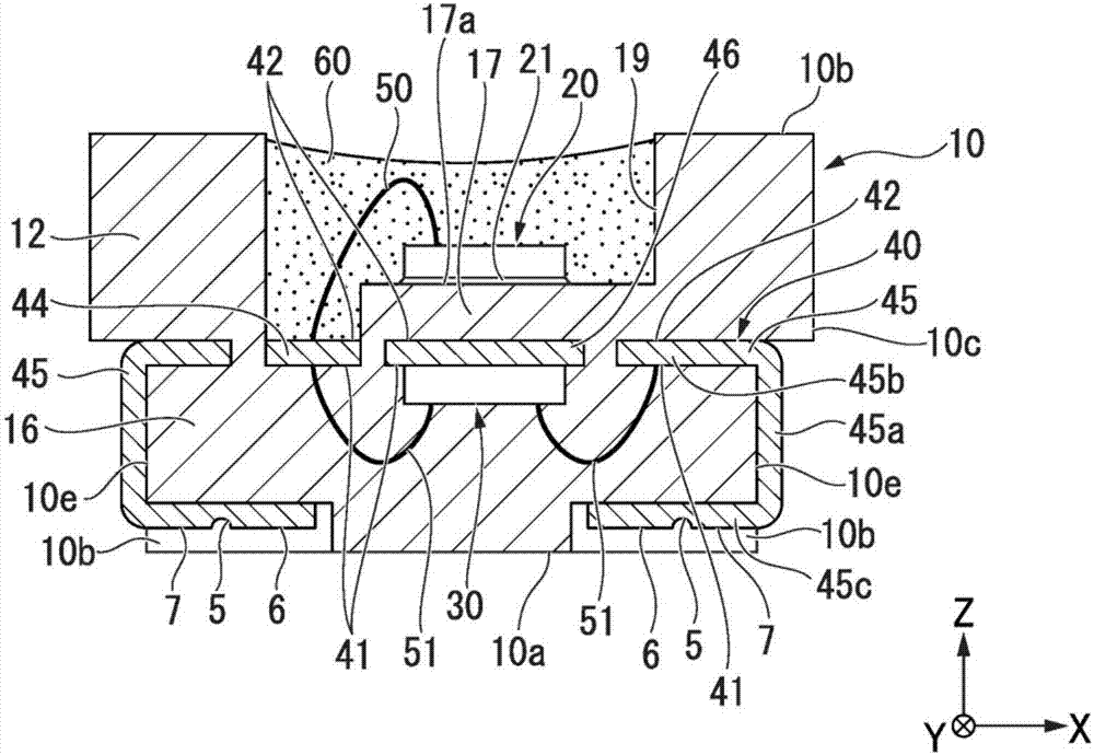
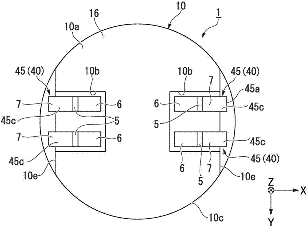
[0046]Figure 1A It is a sectional view of the pressure sensor 1 of the first embodiment. in addition, Figure 1B is a bottom view of the pressure sensor 1. In the description of the pressure sensor 1 of the present embodiment, "up" means the +Z direction, and "down" means the -Z direction. The bottom view is a plan view of the pressure sensor 1 viewed from below.

[0047] Such as Figure 1A , Figure 1B As shown, the pressure sensor 1 of the present embodiment includes a pressure sensor element 20 , a lead frame 40 electrically connected to the pressure sensor element 20 , and a resin base 10 supporting the pressure sensor element 20 and the lead frame 40 . In addition, the pressure sensor 1 has a control element 30 .

[0048] The base body 10 is integrated by embedding the lead frame 40 , the control element 30 , and the bonding wire 51 in the resin of the base body 10 . Thereby, the lead frame 40, the control element 30, and the bonding wire 51 are buried, and can be sh...

no. 2 approach

[0142] Next, a second embodiment will be described.

[0143] Figure 8 It is a bottom view of the pressure sensor 2 of the second embodiment, which is the same as that of the first embodiment Figure 1B corresponding figure.

[0144] In the pressure sensor 2 of the second embodiment, the shape of the concave portion 210b provided on the lower surface 210a of the base body 210 is different. In addition, the pressure sensor 2 of the second embodiment is different in the structure of the groove portion 205 provided in the terminal portion 45c.


PUM

PropertyMeasurementUnit
thicknessaaaaaaaaaa

Abstract

This pressure sensor is provided with: a base body having a housing section; a pressure sensor element disposed in the housing section; and a lead section, which is electrically connected to the pressure sensor element, and which has a terminal section that is provided along the lower surface of the base body, said lead section being exposed to the outside of the base body. The terminal section has a recessed groove section in a second surface, i.e., a surface on the reverse side of a first surface facing the base body, and in the second surface, the recessed groove section demarcates a first region including a leading end of the terminal section, and a second region, which is positioned adjacent to the first region, and which is at a distance from the leading end of the terminal section.

Description

technical field [0001] The invention relates to a pressure sensor and a pressure sensor module. [0002] This application is based on Japanese Patent Application No. 2014-260405 for which it applied in Japan on December 24, 2014, and the priority is claimed, and uses these content here. Background technique [0003] Mobile devices and the like use semiconductor pressure sensors (hereinafter, simply referred to as pressure sensors) utilizing MEMS (Micro Electro-Mechanical Systems: Micro Electro-Mechanical Systems) technology. Such a pressure sensor includes, for example, a pressure sensor element, a control element receiving a signal from the pressure sensor element, a lead frame electrically connecting the pressure sensor element and the control element, and a base on which the control element is molded. In recent years, mobile devices such as mobile phones have required a waterproof function, and when a pressure sensor is incorporated in the mobile device, a structure that...

Claims


Application Information

Patent Timeline
Patent Type & Authority Applications(China)
IPC IPC(8): G01L9/00H01L29/84
CPCG01L9/00G01L19/0069G01L19/0654H01L29/84
Inventor 富田道和
Owner THE FUJIKURA CABLE WORKS LTD
Learn More