
Electromagnetic-control hydraulic drive type fully-variable valve mechanism

A technology of electromagnetic control and valve mechanism, which is applied in the direction of engine components, machines/engines, mechanical equipment, etc., can solve the problems that the valve movement parameters cannot be flexibly changed and fixed, and can be easily popularized, reduce pumping loss, and improve power Sexual and economical effects

Active Publication Date: 2017-08-29
JILIN UNIV
View PDF12 Cites 11 Cited by
  • Summary
  • Abstract
  • Description
  • Claims
  • Application Information

AI Technical Summary

Problems solved by technology

[0005] The purpose of the present invention is to overcome the technical problems such as the fixed law of the valve motion of the existing engine and the above-mentioned variable valve technology that cannot flexibly change the valve motion parameters, and provide a simple and reliable structure that can flexibly control the valve timing, valve opening duration and Electromagnetic control of valve lift Hydraulically driven fully variable valve train

Method used


Image

  • Electromagnetic-control hydraulic drive type fully-variable valve mechanism
  • Electromagnetic-control hydraulic drive type fully-variable valve mechanism
  • Electromagnetic-control hydraulic drive type fully-variable valve mechanism

Examples


Embodiment Construction

[0034] Attached below Figure 1-5 The present invention is described in detail:

[0035] Refer to attached figure 1 , 2, 3, 4, 5:

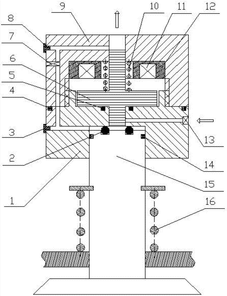
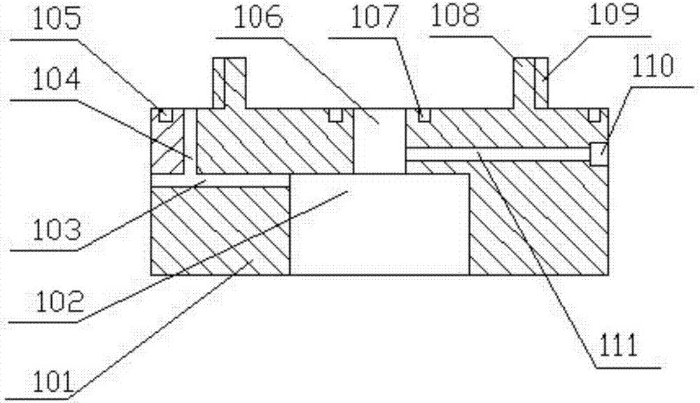
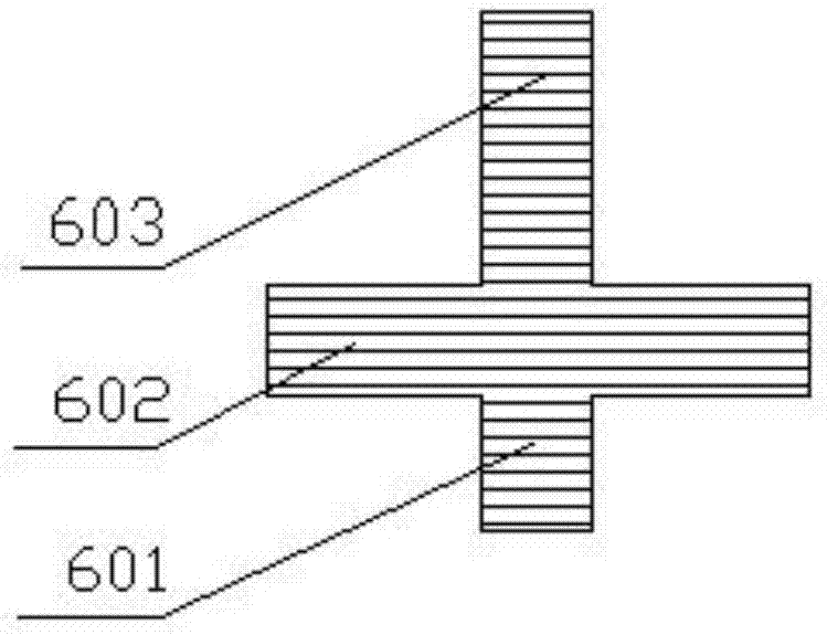
[0036] The present invention consists of control valve lower part 1, buffer ring a2, oil plug a3, sealing ring a4, buffer ring b5, valve core 6, electric control throttle valve 7, oil plug b8, control valve upper part 9, valve core return spring 10, Electromagnetic coil 11, insulating material 12, electric control pressure regulating valve 13, sealing ring b14, valve 15, valve return spring 16 are composed.

[0037] Wherein, the control valve lower part 1 and the control valve upper part 9 are connected through the outer thread 109 of the control valve lower part 1 and the inner thread 906 of the control valve upper part 9;

[0038] The buffer ring a2 is placed in the ring groove d1502 on the top of the valve 15 to provide buffering effect for the seat of the valve 15;

[0039] The oil plug a3 is placed outside the low-pressure oil passage a10...


PUM


Abstract

The invention belongs to the technical field of engines, and relates to an electromagnetic-control hydraulic drive type fully-variable valve mechanism. The electromagnetic-control hydraulic drive type fully-variable valve mechanism consists of a control valve lower part, a valve element, an electric-control throttle valve, a control valve upper part, a solenoid coil, an electric-control pressure regulating valve, a valve, a low-pressure oil path system, a high-pressure oil path system and the like, wherein the solenoid coil is electrified to close the valve element, so that the high-pressure oil path system is opened, the low-pressure oil path system is closed, and high-pressure oil drives the valve to open; the solenoid coil is interrupted, and the valve element is returned, so that the high-pressure oil path system is closed, the low-pressure oil path system is opened and the valve drops; electrifying moment and electrifying duration of the solenoid coil can control valve timing and opening duration; the electric-control pressure regulating valve regulates oil pressure of the high-pressure oil path system, so that valve lift can be controlled; and the electric-control throttle valve regulates effective circulation area of the low-pressure oil path system, so that dropping speed of the valve can be controlled, and impact is reduced. The electromagnetic-control hydraulic drive type fully-variable valve mechanism can realize fully-variable valve motion parameter control, optimizes an engine working process, and is flexible to control; and the electromagnetic-control hydraulic drive type fully-variable valve mechanism is simple in structure, is convenient to manufacture and is easy to popularize.

Description

technical field [0001] The invention belongs to the technical field of engines, and in particular relates to an electromagnetically controlled hydraulically driven fully variable valve mechanism. Background technique [0002] The valve mechanism is one of the important components of the internal combustion engine. It plays an important role in realizing the opening and closing timing of the intake and exhaust valves of each cylinder of the engine and controlling the movement law of the valve lift. It is to realize the engine ventilation process and ensure the internal combustion engine. The basis for the work cycle of thermal power conversion to go on again and again. Therefore, whether the engine can work reliably, whether its power and economy can be guaranteed, is closely related to the control of the valve movement law by the valve train during the ventilation process. [0003] Due to the fixed structure of the traditional engine, the valve movement law is fixed during ...

Claims


Application Information

Patent Timeline
Patent Type & Authority Applications(China)
IPC IPC(8): F01L1/34F01L13/04
CPCF01L1/34F01L13/00F01L13/04F01L2013/101Y02T10/12
Inventor 刘宇解方喜洪伟苏岩许允李小平姜北平石卜从冯爽于岐
Owner JILIN UNIV
Learn More