
Construction technology for vibrocompaction of gravel pile of sediment storage dam of lower storage reservoir

A technology of vibrating and crushing stone piles and construction technology, which is applied in soil protection, infrastructure engineering, construction, etc., can solve the problems of long construction period, unsuitable engineering, and high construction cost, and achieve the improvement of overall compactness and pile side friction. The effect of enhanced strength and bonding ability

Active Publication Date: 2017-08-29
浙江华东工程咨询有限公司
View PDF5 Cites 2 Cited by
  • Summary
  • Abstract
  • Description
  • Claims
  • Application Information

AI Technical Summary

Problems solved by technology

The replacement and filling method has a significant effect on improving the compactness of the roadbed, but it has little effect on reducing the total settlement, and requires a large amount of excavation and transportation, which does not conform to the concept of energy conservation and environmental protection; the construction of the foam light soil method requires foaming, stirring, etc. A variety of machinery, complex construction operations, cost even higher than cement mixing pile composite foundation method, and there are problems such as anti-floating and durability, so shallow foundation treatment is not recommended; semi-rigid pile composite foundation technology such as cement mixing pile is relatively mature , but the construction machinery is heavy, so it is not recommended for shallow foundation treatment; rigid pile composite foundations such as prestressed concrete pipe piles and bored piles are the best, but the cost is high, so it is not recommended for shallow foundation treatment; drainage consolidation The method is cost-effective, but the construction period is long, and it is not suitable for projects with tight construction period requirements

Method used


Image

  • Construction technology for vibrocompaction of gravel pile of sediment storage dam of lower storage reservoir

Examples


Embodiment Construction

[0029] The present invention will be described in further detail below in conjunction with the accompanying drawings.

[0030] This specific embodiment is only an explanation of the present invention, and it is not a limitation of the present invention. Those skilled in the art can make modifications without creative contribution to this embodiment according to needs after reading this description, but as long as they are within the protection of the present invention are protected by patent law.

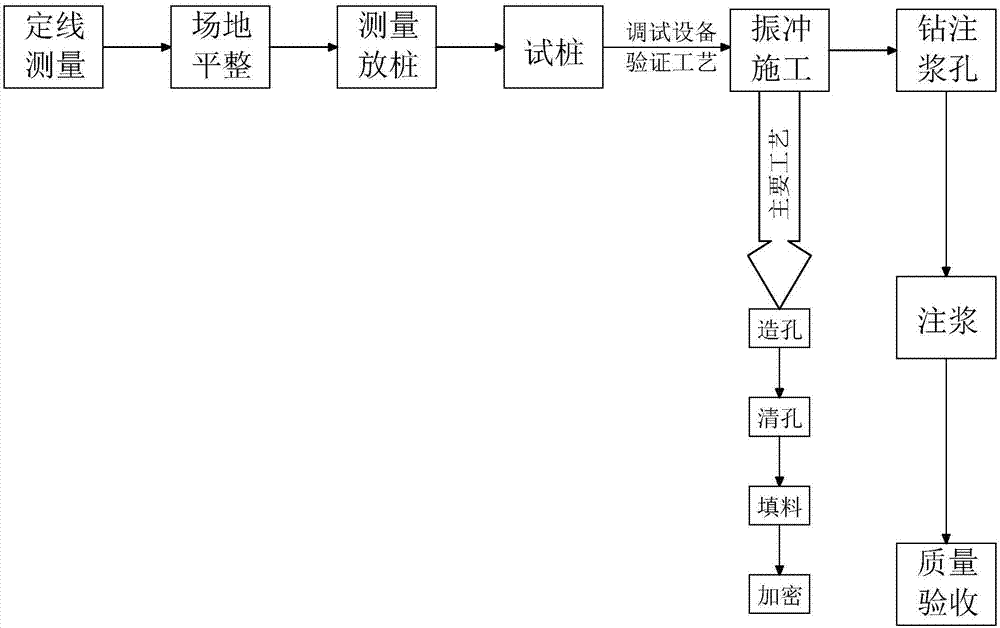
[0031] A construction technique for vibrating gravel piles used in a sand-holding dam of a lower reservoir. The technique includes the following steps:

[0032] S1: Clean up the site, connect the power supply and water source;

[0033] S2: The construction equipment is in place, and the lifting vibrator is aligned with the pile position;

[0034] S3: Hole making:

[0035] (a) Align the vibrator with the pile position, first turn on the pressure water pump, and then start the vibr...


PUM


Abstract

The invention discloses a construction technology for vibrocompaction of a gravel pile of a sediment storage dam of a lower storage reservoir. On one hand, a center grouting hole and circumferential grouting holes are formed in a gravel pile and the periphery of the gravel pile through a drilling machine correspondingly, and when grout permeates into the peripheral loose soil body through the center grouting hole and the circumferential grouting holes, the soil body can be cemented to be a whole body; after solidification, the whole density degree and the effective stress are greatly improved, the nature of the soil body on the periphery of the pile is improved, and the bearing capacity is improved; on the other hand, when the grout permeates towards the pile side, the influence of a mud cake is eliminated to enable the cementing ability of a pile body and the peripheral soil of the pile is enhanced, so that the frictional force of the pile side is improved; and meanwhile, the pile generates a binding effect on the peripheral soil of the pile and prevents the peripheral soil of the pile from deforming in the side direction.

Description

technical field [0001] The invention relates to the technical field of foundation engineering construction, in particular to a construction technique for vibrating gravel piles used in sand-holding dams of lower reservoirs. Background technique [0002] Soft foundations such as beach soil and silty soil are widely distributed in coastal areas and along rivers in my country. Among them, some areas only have soft foundations in shallow layers; some projects have relatively deep soft foundations, but the engineering load is small, and the depth of treatment required is relatively large. Small. According to experience, certain treatment measures must be taken for the soft foundations in the above two cases to meet the settlement and stability requirements. Therefore, in view of the above two types of situations, it is necessary to carry out shallow reinforcement treatment on the weak foundation during the road construction process to control post-construction settlement and ensu...

Claims


Application Information

Patent Timeline
Patent Type & Authority Applications(China)
IPC IPC(8): E02D3/08
CPCE02D3/08
Inventor 张伟任占杰徐俊杰牛昌盛何彦泽
Owner 浙江华东工程咨询有限公司
Learn More