
Punching device for building decorative board

A punching device and architectural decoration technology, applied in woodworking safety devices, wood processing equipment, fixed drilling machines, etc., can solve the problems of low work efficiency, affecting the drilling process, poor stability and accuracy, etc., to achieve convenient operation, The effect of simple structure

Inactive Publication Date: 2017-08-29
广东易享家科技有限公司
View PDF8 Cites 17 Cited by
  • Summary
  • Abstract
  • Description
  • Claims
  • Application Information

AI Technical Summary

Problems solved by technology

[0002] At present, due to its certain strength and convenient processing, boards are widely used in building houses, decorating indoor environments, and making indoor furniture. The traditional hand-held punching machine is used for punching holes, which is easy to carry and easy to operate, but there are defects such as high labor intensity and low work efficiency for workers. In addition, manual punching is easy to cause deviation, poor stability and accuracy. , the existing automatic punching mechanism is in the process of punching wood boards. After the drill bit is worn or damaged during punching, the worker needs to manually replace the drill bit. The replacement operation steps are cumbersome, which affects the drilling process and reduces the drilling efficiency. , can not meet the needs of production use

Method used


Image

  • Punching device for building decorative board
  • Punching device for building decorative board
  • Punching device for building decorative board

Examples


Embodiment Construction

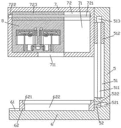
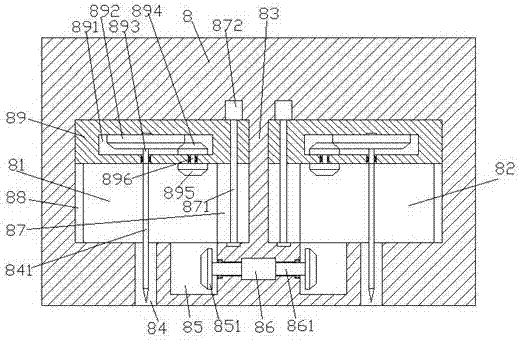
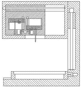
[0022] like Figure 1-Figure 6 As shown, a kind of building decoration plate punching device of the present invention includes a frame composed of a base 6 and a stand 5 and a switching mechanism 7 arranged in the frame, and a switching mechanism 7 is provided in the switching mechanism 7. Cavity 71, the top wall of the switching cavity 71 extends left and right with a first sliding groove 72, and the first sliding groove 72 extends left and right with a first threaded rod 721, and the first threaded rod 721 is threaded and connected There is a first sliding block 723, and the middle position of the bottom end surface of the switching mechanism 7 is provided with a through groove 711 whose top communicates with the switching cavity 71, and the switching cavity 71 is provided with a top and the first sliding block The punching operation mechanism 8 fixedly connected to the bottom end of 723, the first sliding cavity 81 and the second sliding cavity 82 are symmetrically arranged...


PUM


Abstract

The invention discloses a punching device for a building decorative board. The punching device comprises a rack composed of a base and a vertical frame and a switching mechanism arranged in the rack. A switching cavity is formed in the switching mechanism. A first sliding groove is formed in the inner top wall of the switching cavity in a left-right extending manner. A first threaded rod is arranged in the first sliding groove in a left-right extending manner. A first sliding block is connected to the first threaded rod in a threaded fit manner. A through groove with the top communicating with the switching cavity is formed in the middle position of the end of the bottom of the switching mechanism. A punching operation mechanism with the top fixedly connected with the bottom end of the first sliding block is arranged in the switching cavity. A first sliding cavity and a second sliding cavity are symmetrically arranged in the left side and the right side of the punching operation mechanism. A partition is arranged between the first sliding cavity and the second sliding cavity. A second sliding groove is formed in the each of the inner walls of the sides, close to the partition, of the first sliding cavity and the second sliding cavity. A third sliding groove is formed in each of the inner walls of the sides, far away from the partition, of the first sliding cavity and the second sliding cavity. The punching device is simple in structure, convenient to operate, high in safety, fast in maintenance speed and capable of improving the punching efficiency and the punching accuracy.

Description

technical field [0001] The invention relates to the technical field of building decoration processing equipment, in particular to a building decoration plate punching device. Background technique [0002] At present, due to its certain strength and convenient processing, boards are widely used in building houses, decorating indoor environments, and making indoor furniture. The traditional hand-held punching machine is used for punching holes, which is easy to carry and easy to operate, but there are defects such as high labor intensity and low work efficiency for workers. In addition, manual punching is easy to cause deviation, poor stability and accuracy. , the existing automatic punching mechanism is in the process of punching wood boards. After the drill bit is worn or damaged during punching, the worker needs to manually replace the drill bit. The replacement operation steps are cumbersome, which affects the drilling process and reduces the drilling efficiency. , cannot...

Claims


Application Information

Patent Timeline
IPC IPC(8): B27C3/04B27G21/00
CPCB27C3/04B27G21/00
Inventor 何纪全
Owner 广东易享家科技有限公司
Learn More