
Intelligent laying and recovery device for unmanned ship

An unmanned boat, intelligent technology, applied in the direction of ships, davits, transportation and packaging, can solve the problems of occupying too much deck space, long operation time, large size of the hanging cage, etc., to improve the efficiency of deployment and recovery, Reduce labor intensity and good environmental adaptability

Active Publication Date: 2017-08-25
SHANGHAI UNIV
View PDF6 Cites 20 Cited by
  • Summary
  • Abstract
  • Description
  • Claims
  • Application Information

AI Technical Summary

Problems solved by technology

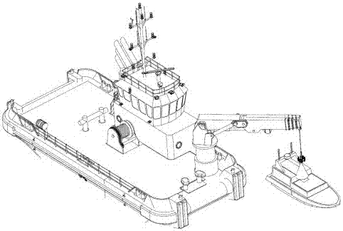
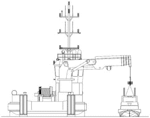
[0004] The hoisting cage recovery method is also the recovery method of the submersible for the recovery of unmanned boats. The principle is to use the lifting mechanism to put the cage into the sea level, and the unmanned boat assists its own power unit to drive into the cage, and then bring the cage The biggest disadvantage of this method is that the volume of the cage is much larger than that of the unmanned boat, and it takes up too much deck space on the deck of the mother ship.
If the control of the power unit is not very good, collisions may occur during the recovery process, requiring high control accuracy, and the disadvantages are too obvious
[0005] The recovery method of the pinball tethered unmanned boat is to use the pinball on the unmanned boat to throw a guide cable to the deck of the ship, and then guide the hook into the lifting point of the unmanned boat along the guide cable. This method is simple and reliable. It is also high, but it requires human participation. It is still very difficult to introduce unmanned boat lifting points under high sea conditions, the degree of intelligence is low, and the operation time is long

Method used


Image

  • Intelligent laying and recovery device for unmanned ship
  • Intelligent laying and recovery device for unmanned ship
  • Intelligent laying and recovery device for unmanned ship

Examples


Embodiment Construction

[0021] The specific embodiments of the present invention will be further described below in conjunction with the accompanying drawings.

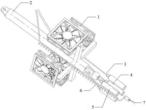
[0022] Such as Figure 1 to Figure 4 As shown, an unmanned boat intelligent deployment and recovery device includes a hoisting tracking mechanism and a clamping mechanism for the central lifting point of the unmanned boat. The hoisting tracking mechanism includes: a vector frequency conversion fan 1, and a rapid ejection telescopic rod assembly 2 , laser indicator light 3, camera 4, laser rangefinder 5, spotlight indicator light 6, docking locking and unlocking induction head 7, the upper part of the fast ejection telescopic rod assembly 2 is provided with a hook connected to the mother ship, and the lower part is provided with Cross bracket, four vector frequency conversion fans 1 are fixed on the cross bracket at the bottom of the rapid ejection telescopic rod assembly 2, and two vector frequency conversion fans 1 are respectively arranged...


PUM


Abstract

The invention discloses an intelligent laying and recovery device for an unmanned ship. The intelligent laying and recovery device for the unmanned ship comprises a hoisting and tracing mechanism and a clamping device for a center lifting point of the unmanned ship. The hoisting and tracing device comprises four vector frequency conversion fans, a rapid ejection telescopic rod assembly, a laser indicator lamp, a camera, a laser rangefinder, a spotlight indicator lamp, and a butt-joint locking and unlocking sensing head; a lifting hook connected with a mother ship is arranged on the upper portion of the rapid ejection telescopic rod assembly, and a cross-shaped fixing frame is mounted on the lower portion of the rapid ejection telescopic rod assembly; the four vector frequency conversion fans are fixed to the cross-shaped fixing frame on the lower portion of the rapid ejection telescopic rod assembly, two vector frequency conversion fans for providing horizontal tracing power are arranged at the X-axis and the Y-axis; the laser indicator lamp, the camera, the laser rangefinder and the spotlight indicator lamp are correspondingly fixed through a mounting frame at the tail of the rapid ejection telescopic rod assembly; the camera is provided with X-axis and Y-axis scales, and the vector frequency conversion fans correspond to the directions of the X-axis and Y-axis scales in the camera separately; and the butt-joint locking and unlocking sensing head is mounted in a groove at the rear end of the rapid ejection telescopic rod assembly.

Description

technical field [0001] The invention relates to an intelligent deployment and recovery device for unmanned boats. Background technique [0002] At present, domestic and foreign drone deployment and recovery mainly include ship mechanical arm (articulated arm type), hanging cage type, pinball tethered type, etc. [0003] The ship's mechanical arm (articulated arm type) uses a long mechanical arm to extend into the water and dock with the lifting point of the unmanned boat. This method draws on the lifting methods of most submersibles at home and abroad, such as Russia's 6000-meter "MIR" and the United States. China's "Alvin" submersible, the French "Nautilus" and Japan's "Deep Sea 2000" and "Deep Sea 6500" and other submersibles all use this articulated arm method. Although the method is simple in concept, has a high success rate, and has many technical supports. However, a defect of this method is that the expansion rod of the equipment is too bulky, takes up a large amoun...

Claims


Application Information

Patent Timeline
IPC IPC(8): B63B23/00B63B23/02
CPCB63B23/00B63B23/02
Inventor 刘明确罗均谢少荣彭艳李恒宇
Owner SHANGHAI UNIV
Learn More