
Profile surface slotting device

A technology of grooving and profile, which is applied in the direction of planer, metal processing equipment, manufacturing tools, etc., can solve the problems that affect the quality of profile processing, cannot meet the needs of production and processing, and the difficulty of grooving tools, etc., to achieve a reasonable structural design Effect

Inactive Publication Date: 2017-08-25
海宁市波菲特进出口有限公司
View PDF0 Cites 7 Cited by
  • Summary
  • Abstract
  • Description
  • Claims
  • Application Information

AI Technical Summary

Problems solved by technology

During the processing and use of the existing profiles, the surface of the profiles needs to be grooved according to the needs of connection and use, so that the profiles can be connected conveniently and the firmness of the profile connection can be improved. During the grooving process of the existing profiles, it is necessary to use The grooving tool cuts the surface of the profile continuously and reciprocatingly so that the surface of the profile can be grooved. It is difficult for the existing grooving device to drive the grooving tool to reciprocate and translate smoothly and conveniently, and the grooving tool is difficult to adjust according to the needs of use. , it is difficult for the existing profile placing device to place the profile stably and firmly, resulting in the translational swing of the profile during the processing, which affects the quality of the profile processing, and it is difficult for the existing profile placing device to place the profile according to the profile during the processing. The required grooving depth requires the profile to be lifted steadily and step by step, so that the profile cannot be processed in an orderly manner according to the required grooving depth during the entire grooving process, resulting in the need for operators to continuously cut during the entire grooving process. Shut down to adjust the grooving tool, which reduces the efficiency of profile grooving and cannot meet the needs of production and processing

Method used

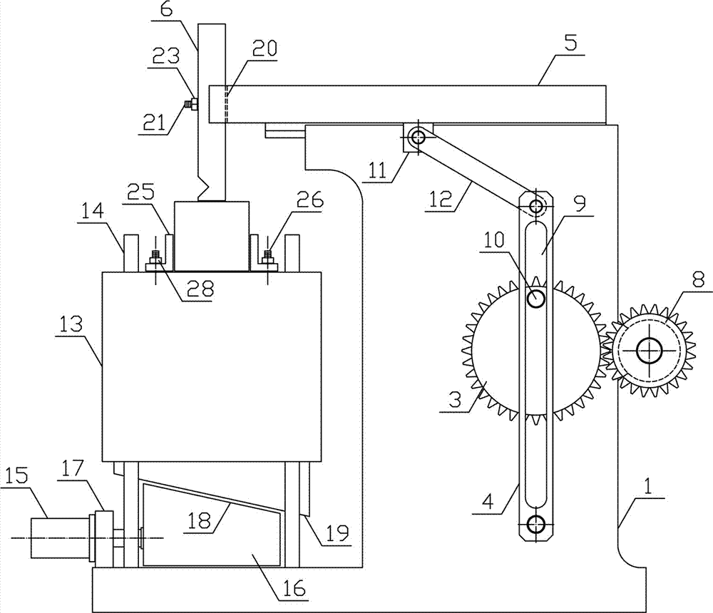
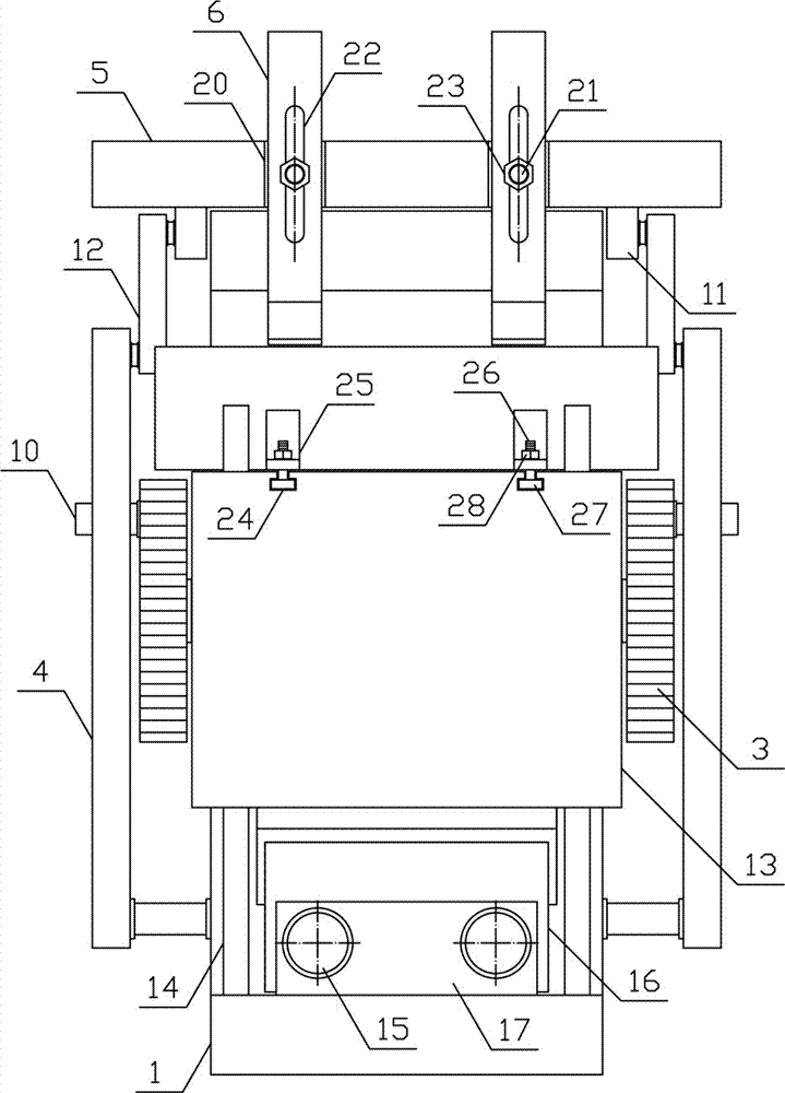
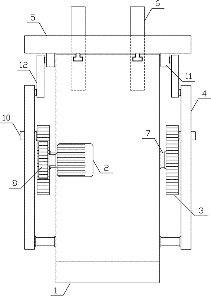

Image

  • Profile surface slotting device
  • Profile surface slotting device
  • Profile surface slotting device

Examples


Embodiment Construction

[0012] In order to further describe the present invention, the specific implementation of a profile surface grooving device will be further described below in conjunction with the accompanying drawings. The following examples are explanations of the present invention and the present invention is not limited to the following examples.

[0013] Such as figure 1 , figure 2 and image 3 As shown, a profile surface grooving device of the present invention includes a fixed support 1, a translation motor 2, a translation gear 3, a swing guide rod 4, a translation support 5, a grooving tool 6 and a material receiving mechanism, and the material receiving mechanism is horizontally arranged on On the upper side of the fixed bracket 1, the middle part of one side of the fixed bracket 1 of the present invention is horizontally connected with a rotating shaft 7, and the two ends of the rotating shaft 7 are respectively vertically and symmetrically provided with translation gears 3, and t...


PUM


Abstract

The invention discloses a profile surface groove cutting device, which belongs to the field of material processing mechanical equipment. The invention includes a fixed bracket, a translation motor, a translation gear, a swing guide rod, a translation bracket, a grooving tool and a material receiving mechanism. The swing guide rods are arranged symmetrically on both sides of the fixed bracket, and the translation bracket is slid on the fixed bracket along the horizontal direction. A translation connecting rod is installed obliquely between the translation push plate and the swing guide rod, and the two sides of one end of the translation support are respectively vertically and symmetrically provided with grooving knives. On the lower side of the material bearing bracket, a push plate slope is arranged on the upper side of the lifting push plate, and a lifting slope compatible with the push plate slope is arranged on the lower side of the material bearing bracket. The invention has a reasonable structural design, can quickly, efficiently and accurately perform groove cutting on profiles, improves the efficiency and quality of profile processing, and meets the needs of production and processing.

Description

technical field [0001] The invention belongs to the field of material processing mechanical equipment, and in particular relates to a profile surface groove cutting device. Background technique [0002] Profiles refer to objects with certain geometric shapes made of metal materials and materials with certain strength and toughness through rolling, extrusion and casting processes. Profiles are widely used in construction and home decoration due to their high strength and high hardness. , mechanical parts, agricultural machinery accessories and manufacturing tools and other fields, with a wide range of applications and many applicable fields. During the processing and use of the existing profiles, the surface of the profiles needs to be grooved according to the needs of connection and use, so that the profiles can be connected conveniently and the firmness of the profile connection can be improved. During the grooving process of the existing profiles, it is necessary to use T...

Claims


Application Information

Patent Timeline
IPC IPC(8): B23D1/10B23D7/06
CPCB23D1/10B23D7/06
Inventor 沈洁
Owner 海宁市波菲特进出口有限公司
Learn More