Calibration system and method of on-line monitoring device for dissolved gas in transformer oil

A monitoring device, transformer oil technology, applied in the direction of material inspection products, etc., can solve the problems of poor monitoring result accuracy, reduced dielectric strength, interference equipment fault monitoring and diagnosis, etc., to ensure accuracy, ensure safety, and avoid false alarms and underreporting effects

Active Publication Date: 2017-08-22
STATE GRID CORP OF CHINA +2
View PDF4 Cites 7 Cited by
  • Summary
  • Abstract
  • Description
  • Claims
  • Application Information

AI Technical Summary

Problems solved by technology

However, because there is no on-site verification of it, the accuracy of its monitoring results is poor, and false positives and missed negatives occur from time to time, which seriously hinders the popularization and application of improved technology.
[0003] At present, there are two main problems in the on-site calibration of the dissolved gas online monitoring device in oil: one is that mechanical impurities are easily introduced during the calibration process, polluting the transformer, and endangering the safety of the equipment; the other is the dissolved gas in the standard oil used for calibration It is difficult to clean, and it is easy to be brought into the transformer body, polluting the transformer oil in the transformer, and interfering with equipment fault monitoring and diagnosis; the third is to flush the oil circuit with new transformer oil. After entering the body, the new transformer oil will react with the old transformer oil to produce sludge. Reduce the insulation strength and endanger the safety of equipment

Method used


Image

  • Calibration system and method of on-line monitoring device for dissolved gas in transformer oil
  • Calibration system and method of on-line monitoring device for dissolved gas in transformer oil

Examples


Embodiment Construction

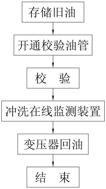
[0029] The present invention will be further described in detail below in conjunction with the accompanying drawings and specific embodiments.

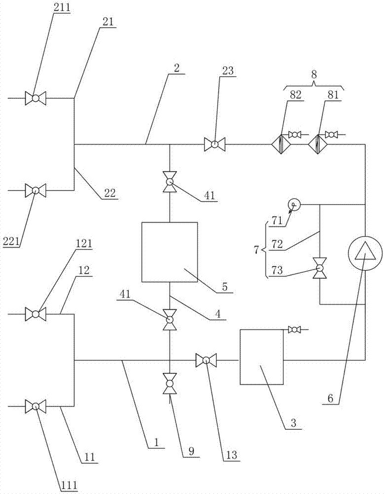
[0030] Such as figure 1As shown, an embodiment of the verification system of the online monitoring device for dissolved gas in transformer oil of the present invention includes an oil inlet main pipe 1 and an oil outlet main pipe 2 connected to each other. The transformer oil inlet pipe 11 connected to the oil outlet of the online monitoring device and the monitoring device oil inlet pipe 12, the transformer oil inlet pipe 11 and the monitoring device oil inlet pipe 12 are respectively equipped with a transformer oil inlet pipe control valve 111 and a monitoring device oil inlet pipe Control valve 121, the outlet end of oil outlet main pipe 2 is provided with transformer oil outlet branch pipe 21 and monitoring device oil outlet branch pipe 22 respectively connected with transformer and online monitoring device oil inlet end, transfor...


PUM


Abstract

The invention provides a calibration system and method of an on-line monitoring device for dissolved gas in transformer oil. The system comprises an oil-taking main tube and an oil-discharging main tube; the oil-taking main tube is provided with a transformer oil-taking branched tube and a monitoring device oil-taking branched tube, and the two branched tubes are provided with a transformer oil taking branched tube control valve and a monitoring device oil taking branched tube control valve; the oil-discharging main tube is provided with a transformer oil-discharging branched tube and a monitoring device oil-discharging branched tube, and the two branched tubes are provided with a transformer oil-discharging branched tube control valve and a monitoring device oil-discharging branched tube control valve; the oil-taking main tube is provided with an oil tank and an oil-taking main tube control valve, an oil-discharging main tube control valve is arranged on the oil-taking main tube, a calibration oil tube is arranged between the oil-taking main tube and the oil-discharging main tube, and the calibration oil tube is provided with an oil calibrating tank and divided oil calibrating control valves. The method comprises the following steps: S1: storage of old oil; S2: opening of the calibration oil tube; S3: calibration; S4: flushing of the on-line monitoring device; S5: oil return of the transformer; S6: finishing. The system and method have the advantages of improved monitoring accuracy, and guarantee of equipment security and dielectric strength.

Description

technical field [0001] The invention mainly relates to the technical field of on-line monitoring of substation equipment, in particular to a calibration system and a calibration method of an on-line monitoring device for dissolved gas in transformer oil. Background technique [0002] When there is an overheating or discharge fault in the transformer, the insulating oil or solid insulating material at the faulty part will decompose small molecular hydrocarbons (such as CH 4 、C 2 h 6 、C 2 h 4 、C 2 h 2 etc.) and other gases (such as H 2 , CO, etc.). The above-mentioned fault characteristic gases will dissolve into the transformer oil, and the internal faults of the transformer oil can be diagnosed by analyzing the concentration of the characteristic fault gases in the oil. With the rapid development of the power industry as a whole to large power grids, large units, and high capacity, the requirements for condition monitoring of key electrical equipment are getting high...

Claims


Application Information

Patent Timeline
Patent Type & Authority Applications(China)
IPC IPC(8): G01N33/28
CPCG01N33/28
Inventor 龚尚昆万涛李臻周舟吴俊杰刘小玲常燕钱晖冯兵何铁祥徐大伟徐松
Owner STATE GRID CORP OF CHINA
Why Eureka
Try Eureka