Bypass heat shield element

A technology of heat shielding and components, used in gas turbine installations, linings of combustion chambers, and annular combustion chambers, which can solve problems such as high pressure loss

Inactive Publication Date: 2017-08-18
SIEMENS AG
View PDF11 Cites 0 Cited by
  • Summary
  • Abstract
  • Description
  • Claims
  • Application Information

AI Technical Summary

Problems solved by technology

[0006] However, the aforementioned solutions have the disadvantage that, for an advantageous inflow of bypass air, an offset in the heat shield element is required, or a higher pressure loss has to be paid due to deflections in the connecting gaps

Method used


Image

  • Bypass heat shield element
  • Bypass heat shield element
  • Bypass heat shield element

Examples


Embodiment Construction

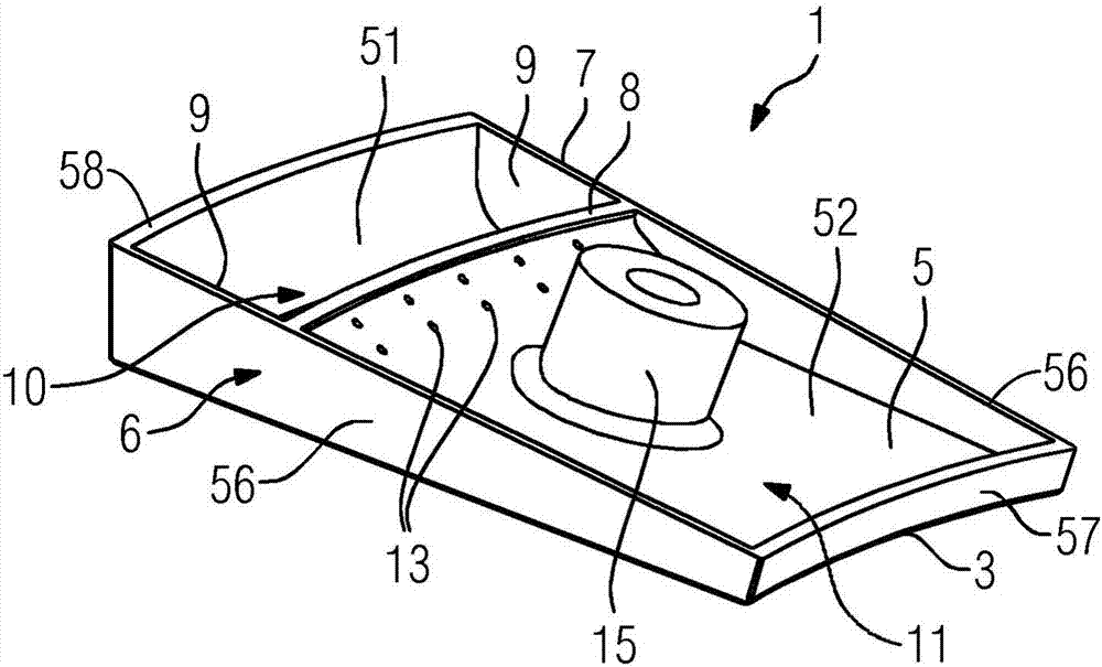
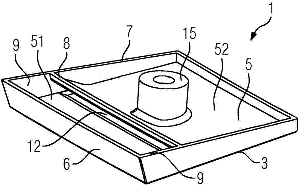
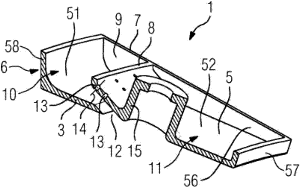
[0037] Figures 1 to 4 A metallic heat shield element 1 according to the invention is shown schematically and by way of example, having a wall 3 with a hot side 4 to which a heat medium can be applied and a cold side 5 opposite the hot side 4 . Figures 1 to 3 shows the cold side 5, Figure 4 The hot side 4 is shown.

[0038] A peripheral edge 6 , which extends beyond the cold side 5 and has a free end 7 facing away from the cold side 5 , adjoins the wall 3 . Here, the wall comprises two opposite first edge sections 56 and a second edge section 57 extending transversely to the two first edge sections 56 and opposite to the second edge sections 57 . Set the third edge section 58. Between the two opposite sides 9 formed by the edge 6, the partition 8 extends from the cold side 5 of the wall 3 up to the level of the free end 7, so that on the cold side 5 of the wall 3 two separate A first chamber 10 and a second chamber 11 , and the first chamber 10 has an open gap 12 from th...


PUM


Abstract

The invention relates to a heat shield element (1), in particular for lining a combustion chamber (2), comprising a wall (3) with a hot face (4), to which a hot medium can be supplied, and a cold face (5), which lies opposite the hot face (4), and comprising a peripheral edge (6), which adjoins the wall (3) and extends outwards beyond the plane of the cold face (5) and which comprises a free end (7) positioned at a distance from the cold face (5). A partition (8) extends from the cold face (5) of the wall (3) to the height of the free end (7) between two opposing sides (9) formed by the edge (6) such that two separate first and second chambers (10, 11) are formed on the cold face (5) of the wall (3), wherein the first chamber (10) has an opening gap (12) from the cold face (5) to the hot face (4). The invention further relates to an annular combustion chamber (2) and a gas turbine system (23).

Description

technical field [0001] The invention relates to a heat shielding element, in particular for the lining of combustion chambers. Furthermore, the invention relates to an annular combustion chamber and a gas turbine arrangement. Background technique [0002] During light-load operation of the gas turbine, the combustion temperature in the combustion chamber drops. At the same time, the temperature in the primary zone, which is important for carbon monoxide emissions, also drops. When the primary zone temperature is below a minimum value, carbon monoxide emissions are increased and the limits of the available light-load range of the gas turbine corresponding to carbon monoxide emissions are reached. [0003] Where there is a legal CO emission limit, the operator of the gas turbine is compelled to shut down the gas if it is not possible for the operator to further reduce the power of his gas turbine without exceeding the CO emission limit at the same time. Turbine. [0004] T...

Claims


Application Information

Patent Timeline
IPC IPC(8): F23R3/06F23R3/50F23R3/60
CPCF23R3/002F23R3/005F23R3/007F23R3/06F23R3/50F23R3/60F23R2900/03041F23R2900/03042F23R2900/03043
Inventor A·伯切尔A·克卢格T·克里格K·M·马勒查Y·穆雅内K-U·席尔德马彻
Owner SIEMENS AG
Why Eureka
Try Eureka