
Capacity allocation method applied to rail transit vehicle-borne hybrid energy storage system

A hybrid energy storage system and capacity allocation technology, applied in the field of multi-energy coupled energy storage capacity allocation, can solve the problems of energy storage components cost, volume increase, low energy density, inability to balance power and energy performance, etc., to achieve reduction Small weight, optimized configuration, and the effect of improving train operation efficiency

Active Publication Date: 2017-08-18
BEIJING JIAOTONG UNIV +1
View PDF8 Cites 10 Cited by
  • Summary
  • Abstract
  • Description
  • Claims
  • Application Information

AI Technical Summary

Problems solved by technology

[0003] Compared with batteries, supercapacitors have the characteristics of high power density, long cycle life, and good temperature characteristics, but low energy density, which cannot meet the needs of rail transit power systems that require high energy
[0004] For a specific energy storage element, its power characteristics and energy characteristics are inherently linked with the energy storage element's own voltage, internal resistance, capacity and other indicators, which are determined by its physical and chemical characteristics. Under the condition of limited manufacturing process, Component performance cannot take into account both power and energy performance. To solve this problem, a single energy storage component can only increase the proportioning capacity, which will lead to an increase in the cost and volume of the energy storage component

Method used


Image

  • Capacity allocation method applied to rail transit vehicle-borne hybrid energy storage system
  • Capacity allocation method applied to rail transit vehicle-borne hybrid energy storage system
  • Capacity allocation method applied to rail transit vehicle-borne hybrid energy storage system

Examples


Embodiment 1

[0047] Embodiment 1. A capacity configuration method applied to a vehicle-mounted hybrid energy storage system for rail transit

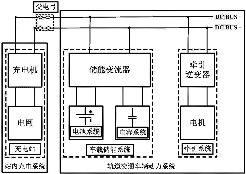
[0048] The vehicle-mounted hybrid energy storage system in this embodiment consists of an energy-type energy storage element lithium-ion battery ( figure 1 The battery system in the battery system) and the power type energy storage element supercapacitor ( figure 1 The capacitive system in the) composition.

[0049] A schematic diagram of the structure of the rail transit vehicle-mounted power system and the charging system in the station in this embodiment, such as figure 1 shown.

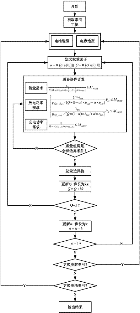
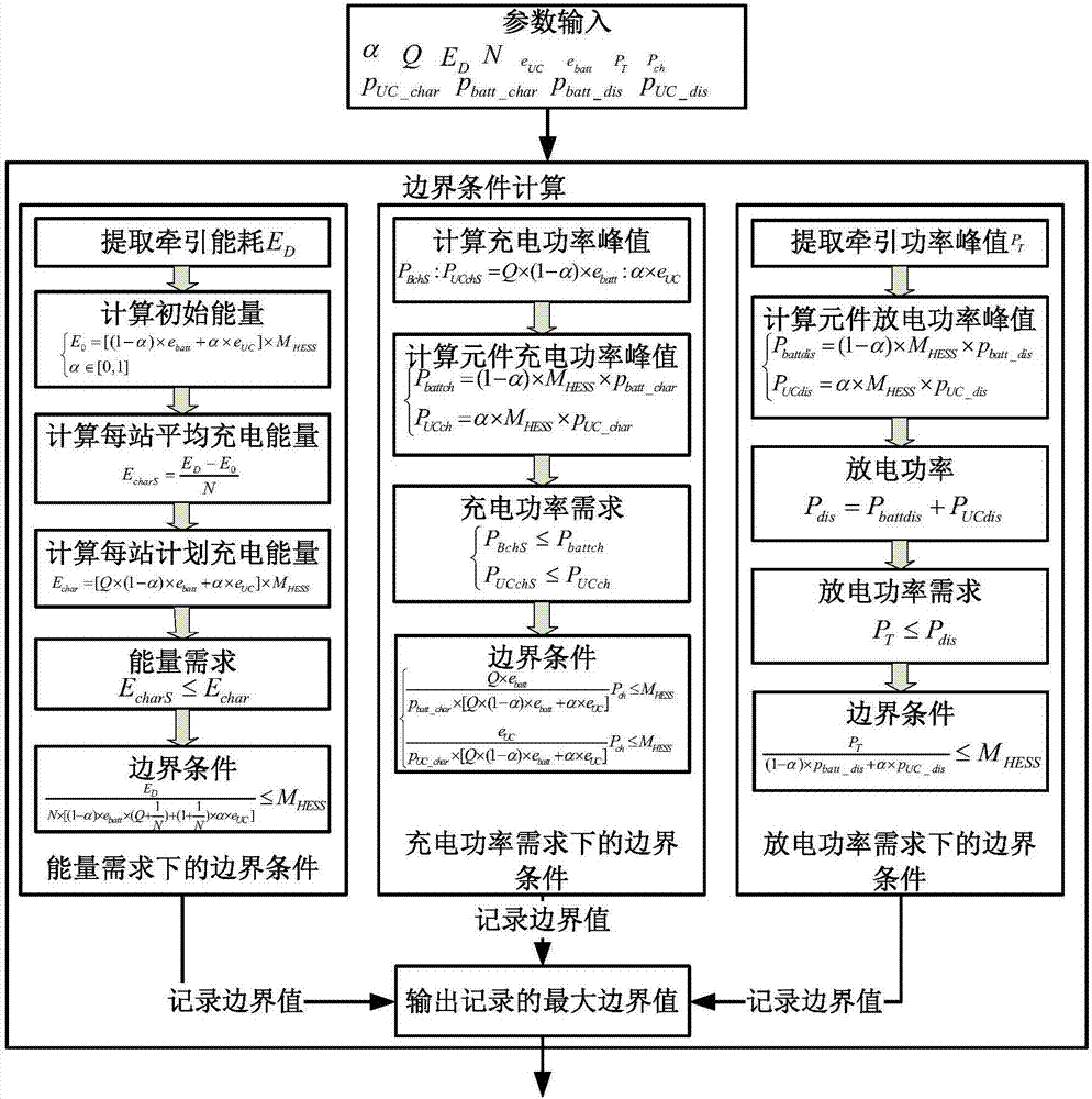
[0050] Such as figure 2 and image 3 As shown, in this embodiment, the capacity configuration method applied to the vehicle-mounted hybrid energy storage system of rail transit includes the following steps:

[0051] Step 1, define the weight weight factor α and the charging energy weight factor Q:

[0052] The weight weight factor α is defined as the proportion o...


PUM


Abstract

The invention relates to a capacity allocation method applied to a rail transit vehicle-borne hybrid energy storage system. The method comprises a step of defining a weight weight factor (alpha) and a charging energy weight factor (Q), a step of substituting the traction condition information of a train, alpha, Q and energy storage component parameters of the vehicle-borne hybrid energy storage system as input into each boundary condition of an energy demand, a charging power demand and a discharge power demand of the vehicle-borne hybrid energy storage system, outputting a boundary value of a total weight of the vehicle-borne hybrid energy storage system separately, and recording a maximum value in three boundary values as the total weight of the vehicle-borne hybrid energy storage system needing to be configured actually in this time of alpha and Q allocation, and a step of obtaining an optimal capacity allocation scheme through the optimized calculation and adjustment of alpha and Q. Accoding to the method, while the train traction is satisfied, with the weight of the vehicle-borne hybrid energy storage system as an optimization target, an optimized capacity allocation scheme with the coupling of different types of energy storage components are made through optimized calculation, and a new way of thinking is provided for the capacity allocation of the vehicle-borne hybrid energy storage system.

Description

technical field [0001] The invention relates to the research on capacity configuration of multi-energy coupled energy storage, in particular to a capacity configuration method applied to rail transit vehicle-mounted hybrid energy storage systems. Background technique [0002] According to the requirements of rail transit power system, the on-board energy storage system with long life, wide temperature range, high rate and other characteristics is selected, which not only responds to the national call for energy saving and environmental protection, but also reduces labor maintenance costs, which is in line with the long-term planning goal of my country's railway construction . Batteries have become the most commonly used energy storage components due to their advantages such as high energy density, modularization, and reliability. However, their disadvantages such as poor temperature characteristics, low cycle life, and low power density limit the working efficiency of battery...

Claims


Application Information

Patent Timeline
Patent Type & Authority Applications(China)
IPC IPC(8): H02J3/28
CPCH02J3/28
Inventor 王占国韦绍远韩伟李雪飞王成涛吴健马泽宇龚敏明
Owner BEIJING JIAOTONG UNIV
Learn More