
Lifting linkage driving device and control method

A driving device and linkage technology, applied in switchgear, switchgear parts, pull-out switchgear and other directions, can solve the problems of increasing cabinet volume and large longitudinal depth of high-voltage switchgear, to simplify the action mechanism, The effect of facilitating the integral design and improving the safety of use

Active Publication Date: 2019-11-12
天津市先智电气设备有限公司
View PDF1 Cites 0 Cited by
  • Summary
  • Abstract
  • Description
  • Claims
  • Application Information

AI Technical Summary

Problems solved by technology

The current technology mostly adopts a horizontal extraction mechanism, and the operator operates horizontally in the front. In order to have sufficient horizontal depth to complete the extraction and push actions, the switch cabinet attachment requires longitudinal depth, especially in medium and high voltage switch cabinets. The withdrawable structure makes the longitudinal depth of the high-voltage switchgear larger and increases the volume of the cabinet

Method used


Image

  • Lifting linkage driving device and control method
  • Lifting linkage driving device and control method
  • Lifting linkage driving device and control method

Examples


Embodiment Construction

[0035] The present invention will be described in further detail below in conjunction with the accompanying drawings and specific embodiments. It should be understood that the specific embodiments described here are only used to explain the present invention, not to limit the present invention.

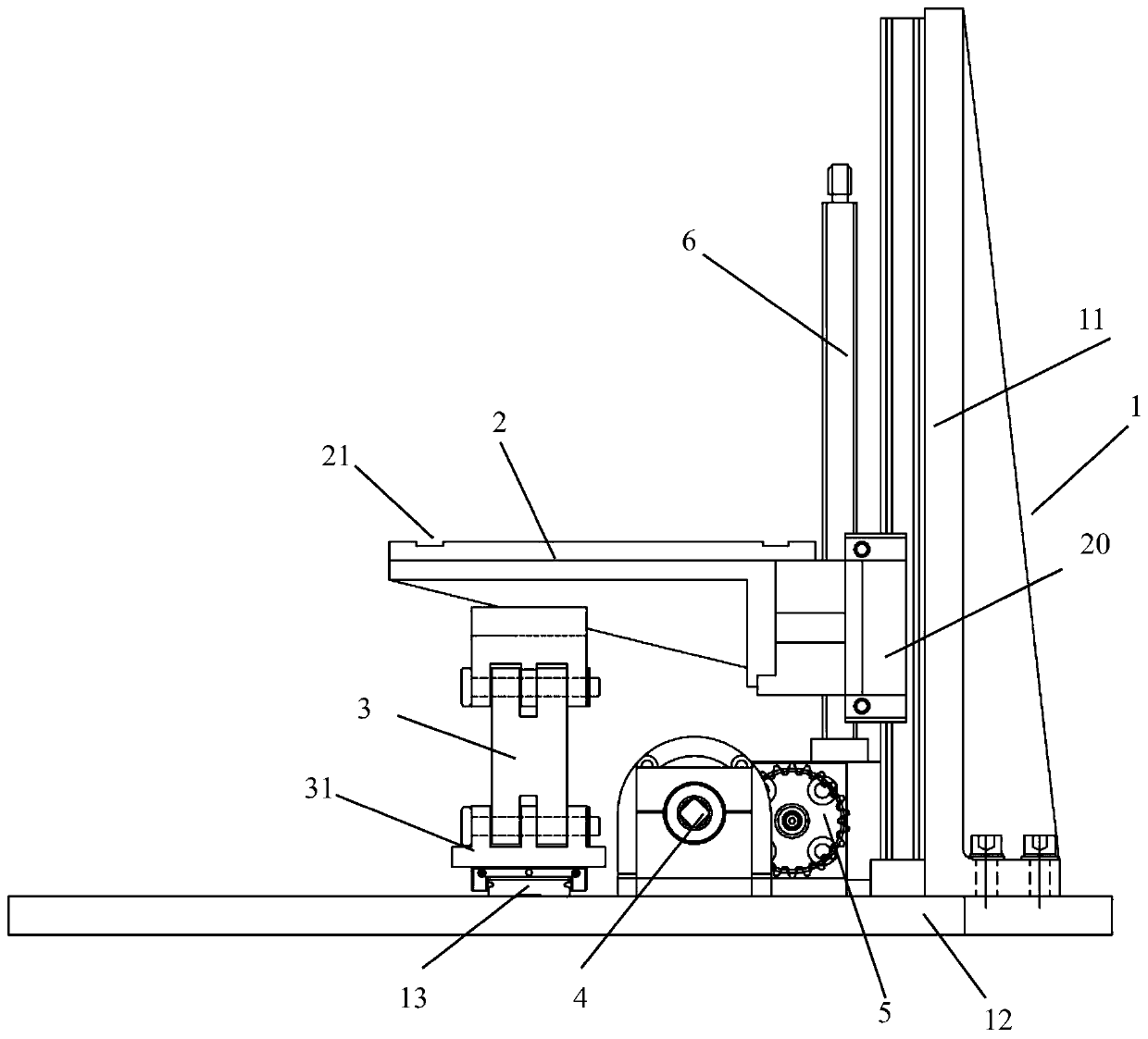
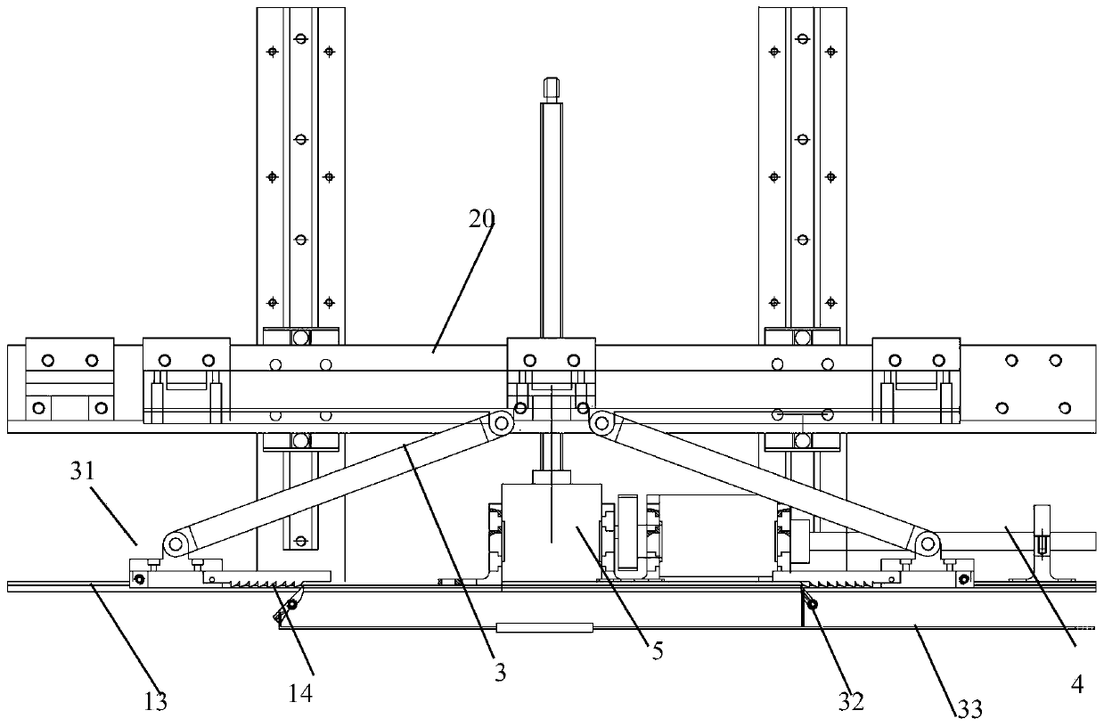
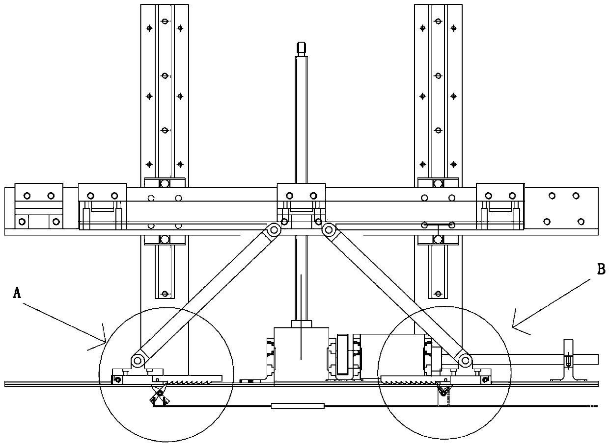
[0036] Such as Figure 1-7 As shown, the lifting linkage driving device of the present invention includes a bracket with a vertical beam in the middle, corresponding to two lifting mechanisms arranged on both sides of the vertical beam 11 of the bracket 1 and two translational driving mechanisms corresponding to the lifting mechanism, That is, the lifting mechanism and the translation drive mechanism are provided in one-to-one correspondence, and the lifting mechanism includes a supporting plate 2 driven to lift vertically, two support arms 3 arranged in a figure-eight shape hinged below the supporting plate, and The lower ends of the arms are mated and connected to the bottom track ...


PUM


Abstract

The invention discloses an elevating linkage type drive device comprising a bracket with a vertical beam arranged in the middle, elevation mechanisms arranged at the two sides of the vertical beam of the bracket, and locking mechanisms for locking lower ends of two support arms tightly to prevent separation. Translation drive mechanisms include linkage pins, fan-shaped gear wheels, and racks; each linkage pin is fixedly arranged at one side of each carrying plate and extends horizontally; the fan-shaped gear wheels fixedly arranged at the bracket in a rotatable manner are provided with guiding slots matching the linkage pins; and the racks are engaged with the fan-shaped gear wheels and are fixedly connected with to-be-driven translation parts. According to the invention, actuator mechanisms are arranged at the liftable carrying plates, so that the height space is utilized fully and the actuating mechanisms are simplified. Moreover, with linkage of the elevation mechanisms and the translation drive mechanisms, synchronous driving of the to-be-driven translation parts is realized, so that overall designing can be realized conveniently and the usage security can be improved.

Description

technical field [0001] The invention relates to the technical field of dual-power switch equipment and a switch cabinet thereof, in particular to a lifting linkage driving device and a control method. Background technique [0002] In the known field of power distribution technology, the withdrawable mechanism has been widely used due to its characteristics of easy operation, convenient maintenance and replacement. The current technology mostly adopts a horizontal extraction mechanism, and the operator operates horizontally in front of the operator. In order to have sufficient horizontal depth to complete the extraction and push actions, the switch cabinet attachment requires longitudinal depth, especially in medium and high voltage switch cabinets. The extraction structure makes the longitudinal depth of the high-voltage switchgear larger and increases the volume of the cabinet. [0003] Now, the space required for power supply is getting smaller and smaller, but the load o...

Claims


Application Information

Patent Timeline
Patent Type & Authority Patents(China)
IPC IPC(8): H02B11/127H02B11/02
CPCH02B11/02H02B11/127
Inventor 王平王金杰
Owner 天津市先智电气设备有限公司
Learn More