
Built-in self-test circuit, built-in self-test system and built-in self-test method for flash memory

A built-in self-test, flash memory technology, applied in static memory, instruments, etc., can solve the problem of difficulty in flash memory testing, and achieve the effect of short test time, simple test process, and reduction of the number of pins

Inactive Publication Date: 2017-08-18
WUHAN XINXIN SEMICON MFG CO LTD
View PDF8 Cites 8 Cited by
  • Summary
  • Abstract
  • Description
  • Claims
  • Application Information

AI Technical Summary

Problems solved by technology

[0004] The purpose of the present invention is to provide a kind of built-in self-test circuit, system and method for flash memory, to solve the problem that existing flash memory test is difficult

Method used


Image

  • Built-in self-test circuit, built-in self-test system and built-in self-test method for flash memory
  • Built-in self-test circuit, built-in self-test system and built-in self-test method for flash memory
  • Built-in self-test circuit, built-in self-test system and built-in self-test method for flash memory

Examples


Embodiment 1

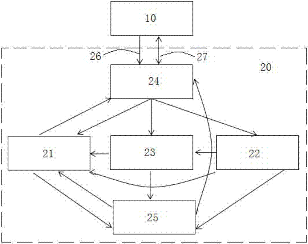
[0055] This embodiment provides a built-in self-test circuit for flash memory, the built-in self-test circuit 20 for flash memory is connected between the test machine 10 and the test flash memory, the built-in self-test circuit for flash memory The circuit 20 includes a self-reading test module 21, a self-erasing test module 22, a self-programming test module 23 and a command conversion module 24, wherein: the self-reading test module 21 is used to test the read operation of the flash memory, and Send the read test result to the command conversion module 24; the self-erasing test module 22 is used to test the erase operation of the flash memory, and send the erase test result to the command conversion module 24; Self-programming test module 23 is used for testing the programming operation of described flash memory, and programming test result is sent to described command conversion module 24; Described command conversion module 24 is used for sending the test order that descri...

Embodiment 2

[0066] This embodiment provides a built-in self-test system for flash memory. The built-in self-test system for flash memory includes a test machine 10 and a built-in self-test circuit 20 for flash memory. The built-in self-test circuit 20 is connected between the test machine 10 and the test flash memory; the built-in self-test circuit 20 for the flash memory includes a self-reading test module 21, a self-erasing test module 22, a self-programming test Module 23 and command conversion module 24, wherein: the test machine is used to send a test command to the command conversion module; the command conversion module is used to send the test command input by the test machine to the self-reading Get the test module, the self-erasing test module and the self-programming test module; the self-reading test module 21 is used to test the read operation of the flash memory, and send the read test result to the command conversion Module 24; the self-erase test module 22 is used to test ...


PUM


Abstract

The invention provides a built-in self-test circuit, a built-in self-test system and a built-in self-test method for a flash memory. The built-in self-test circuit comprises a self-reading test module, a self-erasing test module, a self-programming test module and a command conversion module, wherein the self-reading test module is used for testing reading operation of the flash memory and sending a reading test result to the command conversion module, the self-erasing test module is used for testing erasing operation of the flash memory and sending an erasing test result to the command conversion module, the self-programming test module is used for testing programming operation of the flash memory and sending a programming test result to the command conversion module, and the command conversion module is used for sending test commands inputted by a test machine to the self-reading test module, the self-erasing test module and the self-programming test module, and sending the reading test result, the erasing test result and the programming test result to the test machine.

Description

technical field [0001] The invention relates to the technical field of semiconductors, in particular to a built-in self-test circuit, system and method for flash memory. Background technique [0002] Embedded flash memory test occupies a considerable proportion in the whole semiconductor chip test. Due to the large size of the flash memory, the test time is long, the test pins are many, the program of the test machine is complicated, the test card pins are occupied, and the test cost is high. The prior art uses a built-in self-test circuit for flash memory to solve the above problems, but the shortening of the test time often results in more pins being occupied. At the same time, during the test, the complexity of the test machine program will also have a relatively large impact on the development and maintenance of the flash memory test. If the test is more comprehensive, the machine program will be very complicated, which makes the development and maintenance of the machi...

Claims


Application Information

Patent Timeline
Patent Type & Authority Applications(China)
IPC IPC(8): G11C29/44G11C29/18G11C29/12G11C29/04
CPCG11C29/44G11C29/04G11C29/12G11C29/1201G11C29/12015G11C29/18G11C2029/0401G11C2029/4402
Inventor 刘峰张迪宇
Owner WUHAN XINXIN SEMICON MFG CO LTD
Learn More