
Projection system

A technology of a projection system and a projection lens, which is applied in the field of projection systems, and can solve problems such as hidden dangers of safe and normal use, and increased volume of the projection system

Active Publication Date: 2017-08-18
QINGDAO HISENSE LASER DISPLAY CO LTD
View PDF9 Cites 7 Cited by
  • Summary
  • Abstract
  • Description
  • Claims
  • Application Information

AI Technical Summary

Problems solved by technology

However, when the working distance of the lens is large, the volume of the projection system will become larger, and if the working components such as the scanning and rotating device are damaged during the working process, the laser light spot will be directly hit on the projection screen, which is harmful to the user. There are extremely hidden dangers in the safety of equipment and the normal use of equipment such as projection screens.

Method used


Image

  • Projection system
  • Projection system
  • Projection system

Examples


Embodiment Construction

[0042] An embodiment of the present invention provides a projection system for eliminating field curvature aberration caused by a projection lens.

[0043] In order to make the purpose, technical solutions and advantages of the present invention clearer, the present invention will be further described in detail below in conjunction with the accompanying drawings. Obviously, the described embodiments are only some of the embodiments of the present invention, rather than all of them. Based on the embodiments of the present invention, all other embodiments obtained by persons of ordinary skill in the art without making creative efforts belong to the protection scope of the present invention.

[0044] The projection system provided by specific embodiments of the present invention will be described in detail below in conjunction with the accompanying drawings.

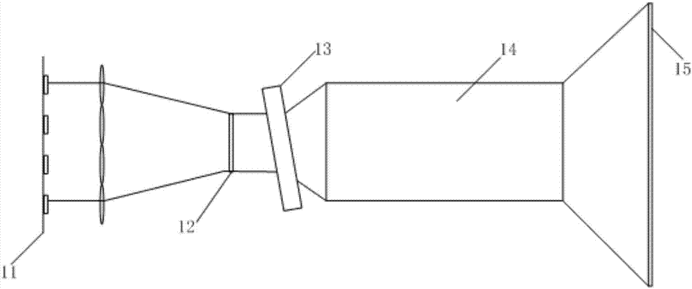
[0045] Such as figure 1 As shown, the projection system provided by the embodiment of the present invention includes: a ...


PUM


Abstract

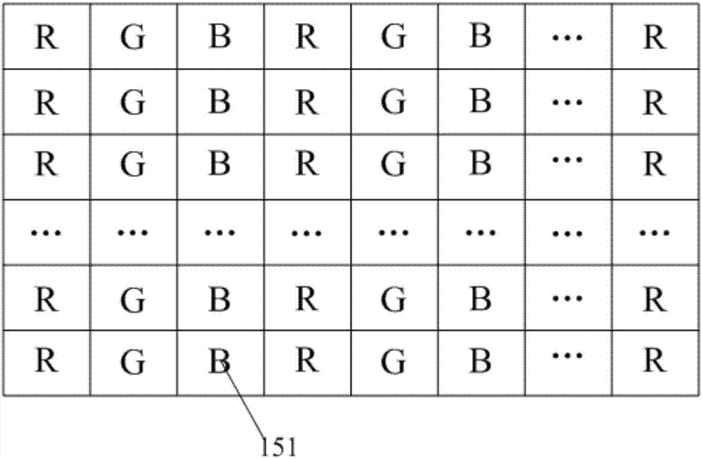
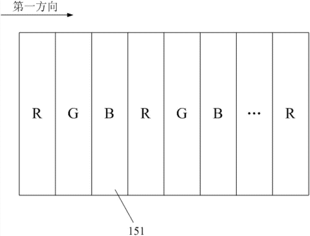
The invention discloses a projection system. The projection system comprises a monochromatic source, a display chip, a galvanometer, a projection lens and a projection screen, wherein the display chip is used for receiving an emergent light beam of the monochromatic source and making the received light beam incident to the galvanometer after modulation, the galvanometer is used for changing a position of the light beam incident to the projection lens so as to change the position of the light beam incident to the projection screen through the projection lens, the projection screen is formed by arranging at least three simulated emission units according to a set rule, and each simulated emission unit is simulated to emit light with special color after illumination of the monochromatic source. The simulated emission unit contained in the projection screen can emit the light with special color after illumination, thus, a clear image can be displayed only by emitting the light ray with special color and special intensity at each pixel position of the projection screen provided by the embodiment of the invention, a curvature field does not exist under a large visual field, the projection lens is only needed to be used for imaging of monochromatic light, and the setting difficulty of the lens is greatly reduced.

Description

technical field [0001] The invention relates to the field of projection technology, in particular to a projection system. Background technique [0002] When the projection system displays an image, it only needs to input the generated analog signal into the projection system through a video cable, that is, the image can be projected on the screen for display. Due to its convenience, it is widely used in the field of display. Laser is a high-brightness, highly directional, and polarized light source. Due to its many advantages, it has been gradually used as a light source in the field of projection display in recent years. [0003] A laser projection system commonly used at present includes several parts such as a projection light source, an optical-mechanical lighting system, a light valve component, a projection lens, and a projection screen. Among them, the projection light source usually includes a laser. In the non-pure color three-color light source, a phosphor wheel ...

Claims


Application Information

Patent Timeline
Patent Type & Authority Applications(China)
IPC IPC(8): G03B21/60
CPCG03B21/60
Inventor 李巍刘显荣郭汝海
Owner QINGDAO HISENSE LASER DISPLAY CO LTD
Learn More