
A Time Response Compensation Method for Thermal Distributed Gas Mass Flowmeter

A technology of gas mass flow and compensation method, which is applied in the field of sensors, can solve the problems of increasing the risk of flow meter signal interference and increasing hardware costs, and achieve the effects of improving dynamic measurement characteristics, shortening response time, and good application prospects

Inactive Publication Date: 2019-05-07
MATERIAL INST OF CHINA ACADEMY OF ENG PHYSICS
View PDF5 Cites 0 Cited by
  • Summary
  • Abstract
  • Description
  • Claims
  • Application Information

AI Technical Summary

Problems solved by technology

Introducing compensation circuits will increase the risk of flowmeter signal interference and increase hardware costs

Method used


Image

  • A Time Response Compensation Method for Thermal Distributed Gas Mass Flowmeter
  • A Time Response Compensation Method for Thermal Distributed Gas Mass Flowmeter
  • A Time Response Compensation Method for Thermal Distributed Gas Mass Flowmeter

Examples


Embodiment

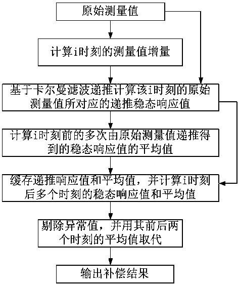
[0046] Such as figure 2 As shown, the time response compensation method of the thermal distributed gas mass flowmeter comprises the following steps:

[0047] (S1) Calculate the measured value increment ΔU=U corresponding to time i according to the original measured value of the thermal distributed gas mass flowmeter i -U i-1 , where U i Indicates the original measured value at time i.

[0048] (S2) According to the two original measured values ​​at the moment i and the fixed measurement time interval Δt at the previous moment, combined with the Kalman filter algorithm to recursively calculate the recursive steady-state response value corresponding to the original measured value at the i moment specifically,

[0049] (S2.1) Establish the state equation and observation equation of the thermal distributed gas mass flowmeter at time i based on the Kalman filter algorithm:

[0050] Equation of state

[0051] Observation Equation E 0 (k)=E(k)+v(k)...(6)

[0052] in, w(...


PUM


Abstract

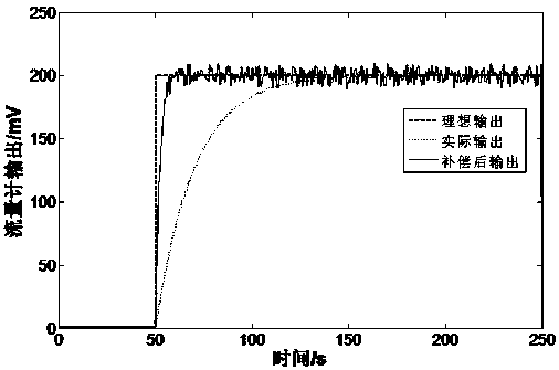
The invention discloses a time response compensation method of a heat distributed gas mass flow meter. The time response compensation method includes: measuring a measured value increment at i moment on the basis of an original measured value; calculating a compensation of a steady state response value by adoption of a kalman filtering algorithm; recursion-calculating an average value of the steady state response values acquired by multiple original measured values before the i moment; eliminating an abnormal value from the acquired data queue; and using the average value of the previous moment and the next moment to replace the abnormal value, and rapidly responding to obtain a final measurement result. Without adding additional hardware, the method can greatly shorten the response time of the heat distributed gas mass flow meter; the experiment confirms that the response time can be shorted by 90%; the measurement response speed of the heat distributed gas mass flow meter can be effectively improved, and the dynamic measurement character of the heat distributed gas mass flow meter can be remarkably enhanced.

Description

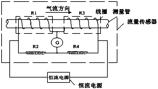
technical field [0001] The invention relates to the technical field of sensors, in particular to a time response compensation method of a thermal distributed gas mass flowmeter. Background technique [0002] The thermal distributed gas mass flowmeter is mainly used for small flow fluid measurement in small and medium-sized pipelines. Its principle is to use the flowing fluid to transfer heat to change the temperature distribution of the measurement tube wall, thereby realizing flow velocity measurement. A typical thermal distributed gas mass flow meter such as figure 1 As shown, on the outer wall of a small-diameter thin-walled measuring tube, two pairs of resistance wires with a high temperature coefficient are wound to form a Wheatstone bridge. The bridge input is a DC constant current. After electrification, the heat generated by the resistance wire heats the measuring tube and the gas inside. When the gas flows through, the heat conducts heat to the fluid in the tube t...

Claims


Application Information

Patent Timeline
Patent Type & Authority Patents(China)
IPC IPC(8): G01F1/76
CPCG01F1/76
Inventor 林奎成唐恺王中成
Owner MATERIAL INST OF CHINA ACADEMY OF ENG PHYSICS
Learn More